EasyManuals Logo

Hypertherm Powermax 65 Field Service Bulletin

Hypertherm Powermax 65
16 pages
To Next Page IconTo Next Page
To Previous Page IconTo Previous Page
Page #6 background imageLoading...
Page #6 background image
DSP boarD rePlacement
4 Field Service Bulletin
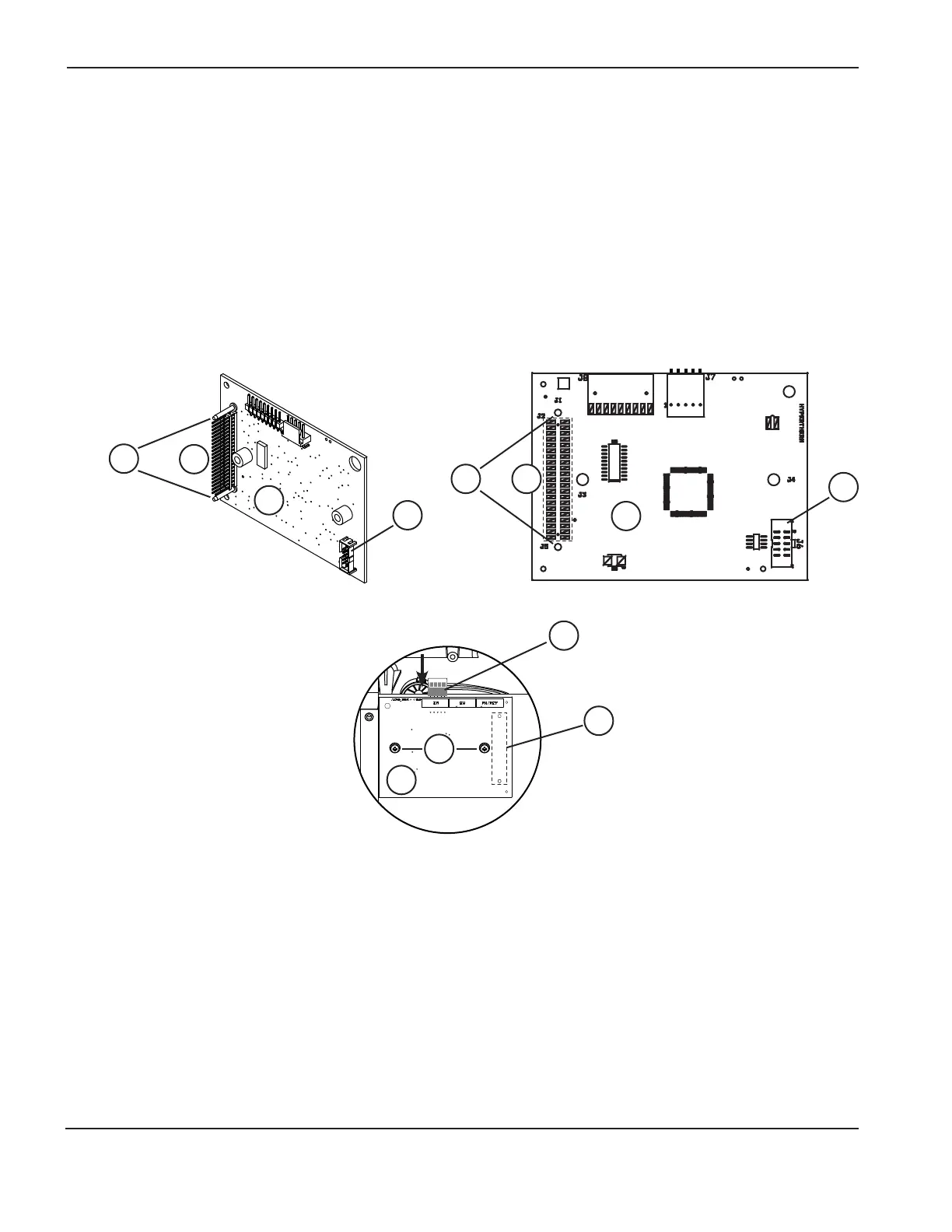
Install the new DSP board
1. Connect the ribbon cable to the ribbon cable connector (6) on the back of the new DSP board (3).
2. Align the two alignment pins (7) with the corresponding holes on the power board.
3. Carefully push the DSP board straight onto the power board. Do not bend the pins (4).
4. Use a #2 Phillips screwdriver to secure the DSP board to the power board using the 2 screws (2).
5. Connect the DSP connector (1) to the top of the DSP board if there is an RS485 communication board installed.
4
4
7
7
6
6
3
3
DSP back view
1
4
2
3
DSP front view

Other manuals for Hypertherm Powermax 65

Questions and Answers:

Question and Answer IconNeed help?

Do you have a question about the Hypertherm Powermax 65 and is the answer not in the manual?

Hypertherm Powermax 65 Specifications

General IconGeneral
Open Circuit Voltage (OCV)300 VDC
Gas SupplyClean, dry, oil-free air or nitrogen
Maximum Cut Capacity (Mild Steel)1" (25 mm)
Input Voltage200-600 V, 1/3-PH, 50/60 Hz
Output Current20 – 65 A
Duty Cycle50% @ 65 A
Recommended Gas Inlet Flow Rate/Pressure6.7 scfm @ 85 psi
Torch Lead Length25 ft (7.6 m)
Maximum Cut Capacity (Aluminum)5/8" (16 mm)
Severance Cut Capacity (Mild Steel)1-1/4" (32 mm)
Maximum Severance Thickness1-1/4 in (32 mm)
Gas TypeAir/Nitrogen
Torch OptionsHand Torch, Mechanized Torch

Related product manuals