EasyManuals Logo

Hypertherm Powermax 65 Field Service Bulletin

Hypertherm Powermax 65
16 pages
To Next Page IconTo Next Page
To Previous Page IconTo Previous Page
Page #7 background imageLoading...
Page #7 background image
DSP boarD rePlacement
Field Service Bulletin 5
Replace the Mylar barrier
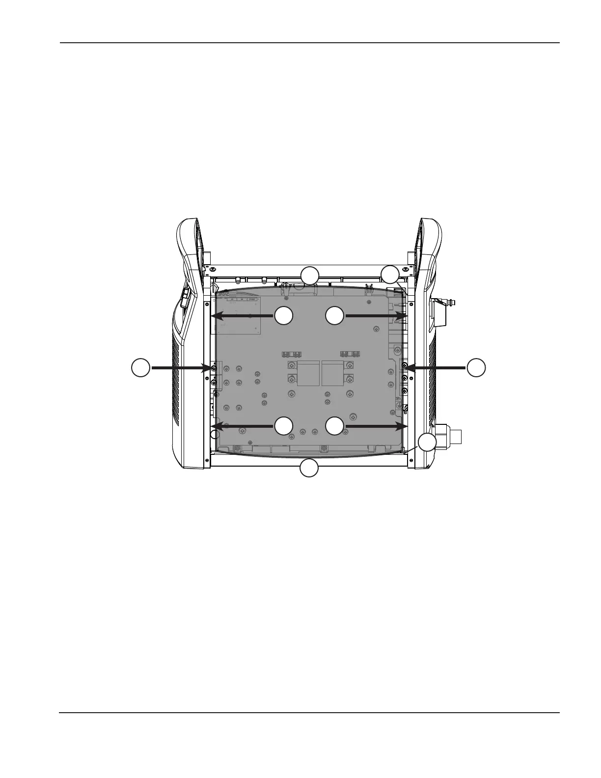
1. Carefully push in the sides (1) of the Mylar barrier so that the barrier bends out slightly at the top and bottom (2).
2. Slide the sides of the Mylar barrier behind the power supply frame (3). Be careful to get the barrier between the
frame and the power wires on the right side of the power board (4).
3. Gently bend the top of the barrier at the perforation so that the top bends over the top of the power supply.
4. Slide the barrier down so that the bottom edge fits inside the power supply frame (5).
1 1
3
3
3
4
5
3
2
2

Other manuals for Hypertherm Powermax 65

Questions and Answers:

Question and Answer IconNeed help?

Do you have a question about the Hypertherm Powermax 65 and is the answer not in the manual?

Hypertherm Powermax 65 Specifications

General IconGeneral
Open Circuit Voltage (OCV)300 VDC
Gas SupplyClean, dry, oil-free air or nitrogen
Maximum Cut Capacity (Mild Steel)1" (25 mm)
Input Voltage200-600 V, 1/3-PH, 50/60 Hz
Output Current20 – 65 A
Duty Cycle50% @ 65 A
Recommended Gas Inlet Flow Rate/Pressure6.7 scfm @ 85 psi
Torch Lead Length25 ft (7.6 m)
Maximum Cut Capacity (Aluminum)5/8" (16 mm)
Severance Cut Capacity (Mild Steel)1-1/4" (32 mm)
Maximum Severance Thickness1-1/4 in (32 mm)
Gas TypeAir/Nitrogen
Torch OptionsHand Torch, Mechanized Torch

Related product manuals