MAINTENANCE
3-4
Service Manual
THEORY OF OPERATION
General
The Powermax800 is a multi-voltage, multi-phase power supply. The two inverter inputs are linked in
parallel
for 208 or 240V on the 208/240/480V units, and for 200 or 230V on the 200/230/400V units.
The inverters are linked in
series
for 480V on the 208/240/480V units, and for 400V on the 200/230/
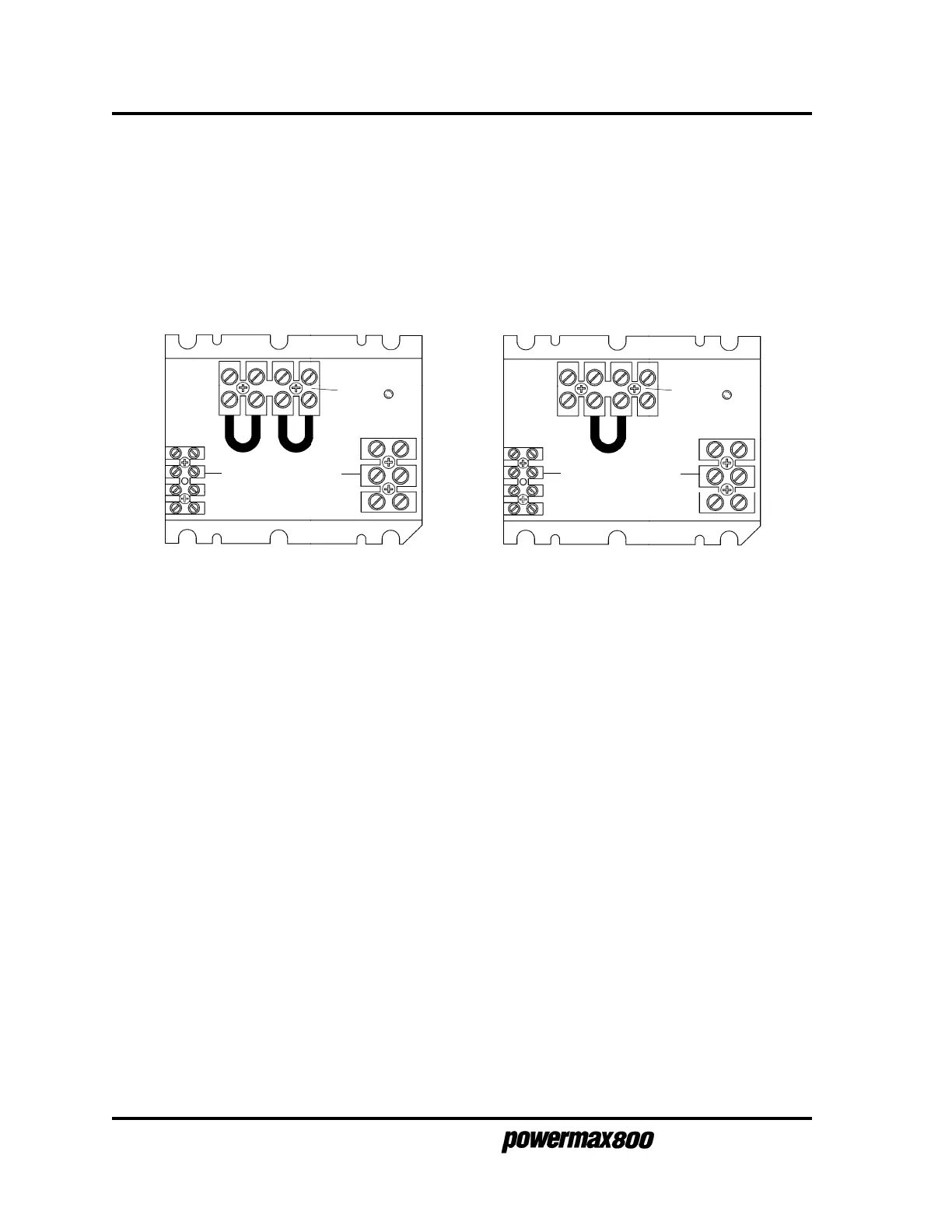
400V units. The inverter links are located in the link box, behind the rear panel at TB3. See Fig. 3-3.
The 400V CE power supply does not have a link box.
Functional Description
Refer to block diagram 3-4, Figure 3-3 and the system wiring diagram. See Section 4: Parts List to
identify system components referenced in this description.
AC power enters power switch S1 from terminal block TB1. The MOV and filter capacitor block
MOV1 provides spike and noise suppression. A "soft start" is implemented via power board resistors
R1 and R2 and relay RL1, and the main contactor CR1. Once the capacitors on the power board are
charged up and incoming power is within limits, the control board turns on the main contactor. Diode
bridge D1 rectifies the AC to DC. The DC voltage is then supplied to the inverters.
Each inverter consists of several components: an isolated gate bipolar transistor (IGBT - Q1 or Q2), a
coil of the power transformer (T2), a current sense transformer (CS1 or CS2), and sections of the
power board. The inverters operate as a pulse width modulator controlled half-bridge circuit. The
inverters are capacitor fed and transformer coupled, switching at 20 KHZ. The inverter outputs are
connected in series, and are rectified by output diodes D2 and D3.
The output circuitry consists of a current sensor CS4 and transfer sensor CS3 located on the control
board, pilot arc relay CR2, and output inductor L1.
The feedback loop operates as follows: The amp adjust pot P1 is first set to the desired value.
Current sensor CS4 measures the actual output current and compares it at the error amplifier with the
user-set current setting. The error amplifier output is an analog indication of how wide the pulse width
should be to maintain the current setting. The error amplifier output is then fed to the pulse width
modulator chip PWM. The pulse width modulator sends the signal to the gate drive board
transformers, and the gate drive boards in turn drive the inverter IGBTs Q1 and Q2.
480V Link on 208/240/480V units
and
400V Link on 200/230/400V units
TB3
TB3
208 or 240V Links on 208/240/480V units
and
200 or 230V Links on 200/230/400V units
TB2 TB1
TB2 TB1
Figure 3-3 Inverter Links
3-96