MAINTENANCE
3-6
Service Manual
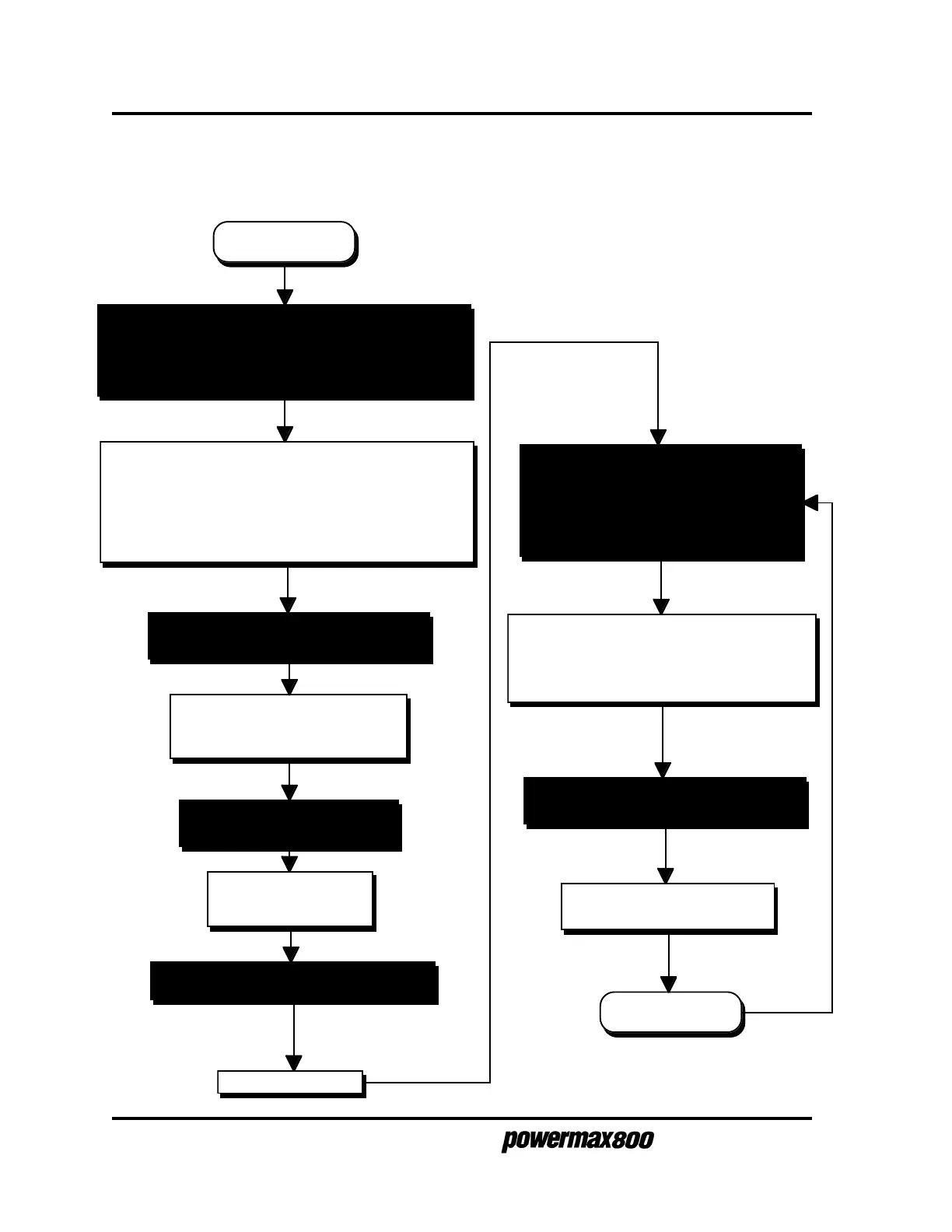
SEQUENCE OF OPERATION
Shaded boxes represent operator action. Clear boxes represent results from operator action.
• Connect gas supply to filter-regulator on power unit
• Apply power at line voltage disconnect box.
• Set power circuit breaker S1 to ON (1).
After five seconds, LINE VOLTAGE and TEMP LEDs
turn off indicating line voltage and transformer
temperatures are within operating limits.
Fan M1 operates and POWER and GAS PRESSURE
LEDs light indicating system is ready for operation.
• Push and hold GAS TEST switch to
check air pressure.
Gas solenoid valve V1 opens to
purge system and to allow setting
of pressure.
• Select cutting current with AMPS knob.
Power circuits ready.
• Connect work cable to workpiece and
position torch on workpiece.
• Depress plasma start switch on hand
torch or remote start switch for machine
torch.
Gas solenoid valve V1 opens and gas flows
Pilot arc relay CR1 closes and pilot arc starts.
Cutting arc transfers to workpiece
Pilot arc relay CR1 opens and pilot arc stops.
• Move torch to make cut. Workpiece
falls away after cut.
Gas solenoid VI closes and gas
flow stops.
System off
• Release GAS TEST switch.
Gas solenoid valve V1
closes. Gas flow stops.
Power circuits ready