Powermax45/45 XP Field Service Bulletin 807990 3
Powermax45/45 XP Snubber Resistor Replacement Kit
9. Remove the screw at J1 that secures the white wire and the screw at J2 that secures the black wire from the
ON/OFF switch to the power board.
10. Stand up the unit again. Tuck out of the way all the wires that you detached.
11. Pull the board straight out from the power supply and set aside.
Proceed to page 7 for further instructions.
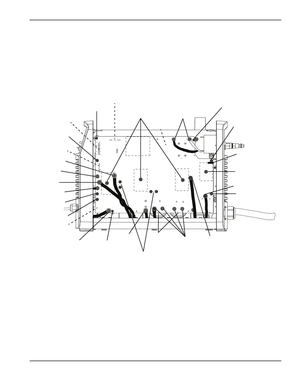
Figure 2 – Newer 200–240 V CSA and 230 V CE power board
TP 19
W
-
+
-
+
TP 18
R
TP 17
B
192 VDC
192 VDC
Heat sink assembly
screw
Ribbon cable (J7)
J10, J12
J13
J14
J16
J17
J19
J22
Heat sink
assembly screw
J3, J4, J5
Retaining screw
IGBT attachment
screws (3)
ON/OFF
switch wires
Retaining screw
Heat sink assembly
screw
Newer boards have a
slot here
J18
Heat sink assembly
screw
Input bridge diode
screw
J6
J2 J1
J15
J20
Retaining
screw
Work lead
connector (J21)
Snubber resistor screws (4)
Pressure relief
vents
Capacitor
screws (4)