EasyManua.ls Logo

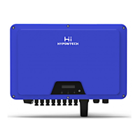
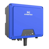
Hypontech HHT-5000 Series User Manual

Hypontech HHT-5000 Series
35 pages
To Next Page IconTo Next Page
Page #1 background imageLoading...
Page #1 background image

Questions and Answers:

Hypontech HHT-5000 Series Specifications

General IconGeneral
Max. Input Voltage600 V
Number of MPPT Trackers2
Efficiency98%
Nominal AC Output Power5000W
Max. AC Output Power5500W
Operating Temperature-25°C to 60°C
ModelHHT-5000 Series

Summary

1. OPERATION MODES INTRODUCTION

2. SYMBOLS ON THE LABEL

3. SAFETY AND WARNINGS

10. COMPATIBLE BATTERY MODELS

4. UNPACKING

3.1 SCOPE OF DELIVERY

Specifies the items included in the inverter's delivery package and checks.

3.2 PRODUCT OVERVIEW

Provides a general description of the inverter's physical dimensions and components.

5. INSTALLING

4.1 INSTALLATION REQUIREMENT

Outlines the necessary environmental and positional requirements for installation.

4.2 MOUNTING LOCATION

Specifies suitable locations and conditions to avoid for mounting the inverter.

4.3 MOUNTING

Details the physical steps and methods for securely mounting the inverter.

4.4 INSTALLING THE PE CABLE

Guides on the proper procedure for installing the protective earth (PE) cable.

6. COMMISSIONING

5.1 SAFETY INSTRUCTIONS

Lists essential safety guidelines and checks before initiating the commissioning process.

5.2 AC, BACK-UP WIRE ASSEMBLY AND CONNECTION

Explains the process for assembling and connecting AC and Back-up electrical wires.

5.2.2 AC SWITCH TYPES

Specifies the required types and ratings for AC circuit breakers.

5.3 BACK-UP WIRE ASSEMBLY AND CONNECTION

Details the procedures for assembling and connecting the Back-up wiring.

5.3.2 BACK-UP SWITCH TYPES

Specifies the required types and ratings for Back-up circuit breakers.

5.4 PV WIRE ASSEMBLY AND CONNECTION

Guides on connecting the PV array wiring correctly to the inverter.

5.5 BATTERY WIRE ASSEMBLY AND CONNECTION

Provides instructions for the correct assembly and connection of battery wiring.

5.6 RESIDUAL CURRENT PROTECTION

Explains the internal residual current protection and recommendations for external devices.

7. COMMUNICATION

6.1 SYSTEM MONITORING VIA DATALOGGER - RS485/WI-FI/GPRS (OPTIONAL)

Details the installation and setup for system monitoring using datalogger options.

6.2 DEMAND RESPONSIVE MODES (DRMS)

Explains the application and availability of Demand Responsive Modes (DRMs).

8. START UP AND OPERATION

7.1 SAFETY CHECK BEFORE START UP

Lists crucial safety checks to perform before energizing and starting the inverter.

7.2 INVERTER LED INDICATORS

Explains the meanings of the different LED indicators on the inverter's display.

7.3 DISPLAY AND CONTROL LOGICS

Details the operational logic and navigation of the inverter's LCD display and controls.

9. DISCONNECTING FROM VOLTAGE RESOURCES

10. TECHNICAL PARAMETERS

11. TROUBLE SHOOTING

EARTH FAULT ALARM

Describes the indication and general cause of an Earth Fault Alarm.

FULL ERROR CODE AND CORRECTIVE MEASURES

Lists specific error codes and provides corrective actions for troubleshooting.

12. SYSTEM MAINTENANCE

13. RESTARTS

Related product manuals