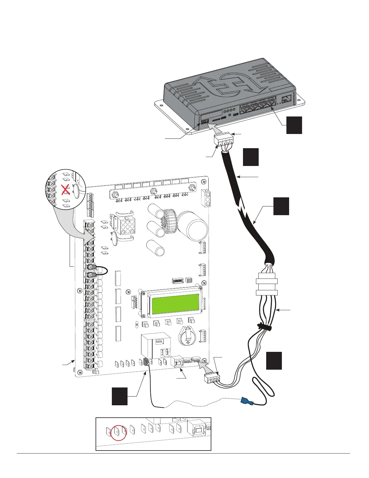
Wiring the HyNet Gateway
COM
COM
COM
COM
COM
COM
COM
COM
STOP
OPEN
RADIO
CLOSE
OPEN
OPEN
PARTIAL
SENSOR 2
EXIT
LOOP
BLOCK
EXIT
IN OBS
LOOP
OUT OBS
LOOP
CENTER
LOOP
COM
+ 24 V
EMERG
OPEN
SHOW
LEDs
R
ADI
O
O
P
T
I
O
NS
E
D
G
E
+24
V
O
P
E
N
C
O
M
DU
A
L G
A
T
E
COM
B
A
U
S
ER
2
C
O
M
N
O
DC
COMMON
TERMINALS
24VDC
24VDC
12VDC
12VDC
24VDC
24VDC
24VAC
24VAC
12VDC
12VDC
SENSOR 3
SENSOR 1
SENSOR
Pin 1,
COM
Installer supplied shielded
cable
NOTE: More detailed
wiring information is
shipped with the HyNet.
NOTE: The Smart DC Controller pin layout changed a
few years ago. On controllers with part numbers
marked MX001457 and MX3037 Revisions A, B, and C,
be sure you're connecting the ying lead to the +24V
spade located under RADIO OPTIONS.
R
A
D
I
O
O
P
T
ION
S
E
D
G
E
+
2
4
V
O
P
E
N
COM
DU
A
L GATE
COM
B
A
U
S
E
R2
COM
N
O
D
C
Drawing is not to scale.
Attach shielded
cable to wire
harness.*
*Measure distance
between HyNet and
Controller connections
for appropriate
shielded cable length.
2
1
Attach to RS-485
port on HyNet.
3
Connect to RS-485
port on Smart DC
Controller.
4
Connect ying
lead to +24V.
Optional +24VDC
if RADIO OPTIONS
+24V is occupied
Wire harness
(supplied in box)
5
Supply
RJ-45 network
connection
HyNet
RS-485 port
Pin 1, +24V
Smart DC Controller
RS-485
Connector
RS-485 ports
USB port
www.SecureOpeners.com | (800) 878-7829 | Sales@SecureOpeners.com
 Loading...