EasyManua.ls Logo

HySecurity Smart Touch User Manual

Default Icon
134 pages
To Next Page IconTo Next Page
Page #1 background imageLoading...
Page #1 background image
Programming and Operations Manual
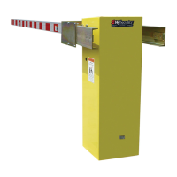
StrongArm
14F, 20, 28, 36, DOT 28
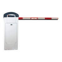
Vehicular barrier gate operator with Smart Touch Controller

Table of Contents

Question and Answer IconNeed help?

Do you have a question about the HySecurity Smart Touch and is the answer not in the manual?

HySecurity Smart Touch Specifications

General IconGeneral
BrandHySecurity
ModelSmart Touch
CategoryGate Opener
LanguageEnglish

Summary

Important Safety Instructions

Barrier Arm Safety and Traffic Control

Warnings for Barrier Arm Safety

Lists key safety warnings for barrier arm use, including vehicle-only access.

Electrical, Grounding, and Battery Safety

Grounding Safety Requirements

Details proper grounding procedures to prevent electrocution and equipment damage.

Proper Grounding and Breather Cap Installation

Gate Operator Installation

Key Installation Steps and Verification

Covers arm attachment, testing, accessory installation, and safety labels.

Power System Configuration

Installing the Earth Ground Connection

Details requirements for a separate earth ground rod for lightning protection and safety.

Power Wiring and Connections

Wiring AC Power Connections

Provides guidance on connecting AC power, including in-rush current and wire sizing.

Wire Sizing and Runs Guidance

Explains wire sizing and distance calculations for optimal electrical service.

StrongArm Wiring Charts for Incoming Power

Charts detailing wire size and maximum distance for various power and horsepower ratings.

AC Power Supply with HyInverter AC

Explains the HyInverter AC option, powered by DC batteries for UPS functionality.

Initial Setup and Controller Navigation

Leveling and Balancing the Gate Arm

Valve Adjustments for Smooth Operation

Adjusting the Pressure Relief Valve

Procedure for adjusting the pressure relief valve to set maximum system hydraulic pressure.

Adjusting the Brake Valve

Explains how to adjust brake valves for smooth gate stopping and movement.

Limit Switch Adjustments

Emergency Override Procedures

Manual Bypass Valve Operation

Details the procedure for manually operating the gate arm in case of power failure.

Entrapment Protection Setup

Install Normally Closed (NC) Sensors

Wire non-contact sensors (photo eyes) to SENSOR terminals for entrapment protection.

Photo Eye Functionality and Alignment

Photo Eye Alignment

Explains how to achieve careful optical alignment for photo eyes and uses the buzzer chirp feature.

Control Panel Component Overview

StrongArm Wiring Diagram

STC and Power Supply Board Overview

Display & Menu Options Navigation

Initial Setup Procedure

Guides on programming the operator after installation and power-up.

Menu Mode and STC Keypad Operation

Menu Mode Navigation

Explains how to navigate through menus and select options using the keypad.

Run Mode and STC Keypad Operation

User Menu Functions

User Menu Table and Settings

Details User Menu items, setting options, tasks, and STC wire connections.

Installer Menu Functions

Installer Menu Table and Settings

Details Installer Menu items, setting options, tasks, and STC wire connections.

Testing the Gate Operator

STC Inputs & Wiring Guide

Overview of STC and Power Supply Board

Smart Touch Controller Inputs

User Relays – Programming Procedure

Bi-Parting & Dual Gate Systems

Dual Gate Wiring Connections

Dual or Sequenced Gates: Requirements

Programming a Dual Gate (Interlocked Pair)

Details programming the Dual Gate (DG) menu item for primary/secondary or Sally Port configurations.

Connecting Sequenced Gates

Vehicle Detector Installation

Hy5A and Hy5B Vehicle Detector Installation

Connecting Hy5A Vehicle Detectors

Photo Eye Installation

Photo Eyes (Non-Contact) Installation

Photo Eye Configuration and Connections

Photo Eye Alignment Feature

Troubleshooting System Malfunctions

System Diagnostic Messages

Explains STC diagnostic messages (Alert, Fault, Error) and how to clear them.

Typical Problems and Troubleshooting Procedures

Troubleshooting Codes: Table 8

Electrical Issues Troubleshooting

General Maintenance Procedures

Smart Touch Analyze and Retrieve Tool (S.T.A.R.T.)

Introduces the S.T.A.R.T. software for gate operator diagnostics and configuration.

Maintenance Tasks

Hydraulic System Maintenance

StrongArm Operator Maintenance Schedule

Wiring HySecurity Sensors: Smart Touch

StrongArm Installer Checklist

Specifications for StrongArm Models

Related product manuals