MX3657-01 Rev. D ©2020
86 hysecurity.com | 800-321-9947 StrongArm Programming and Operations
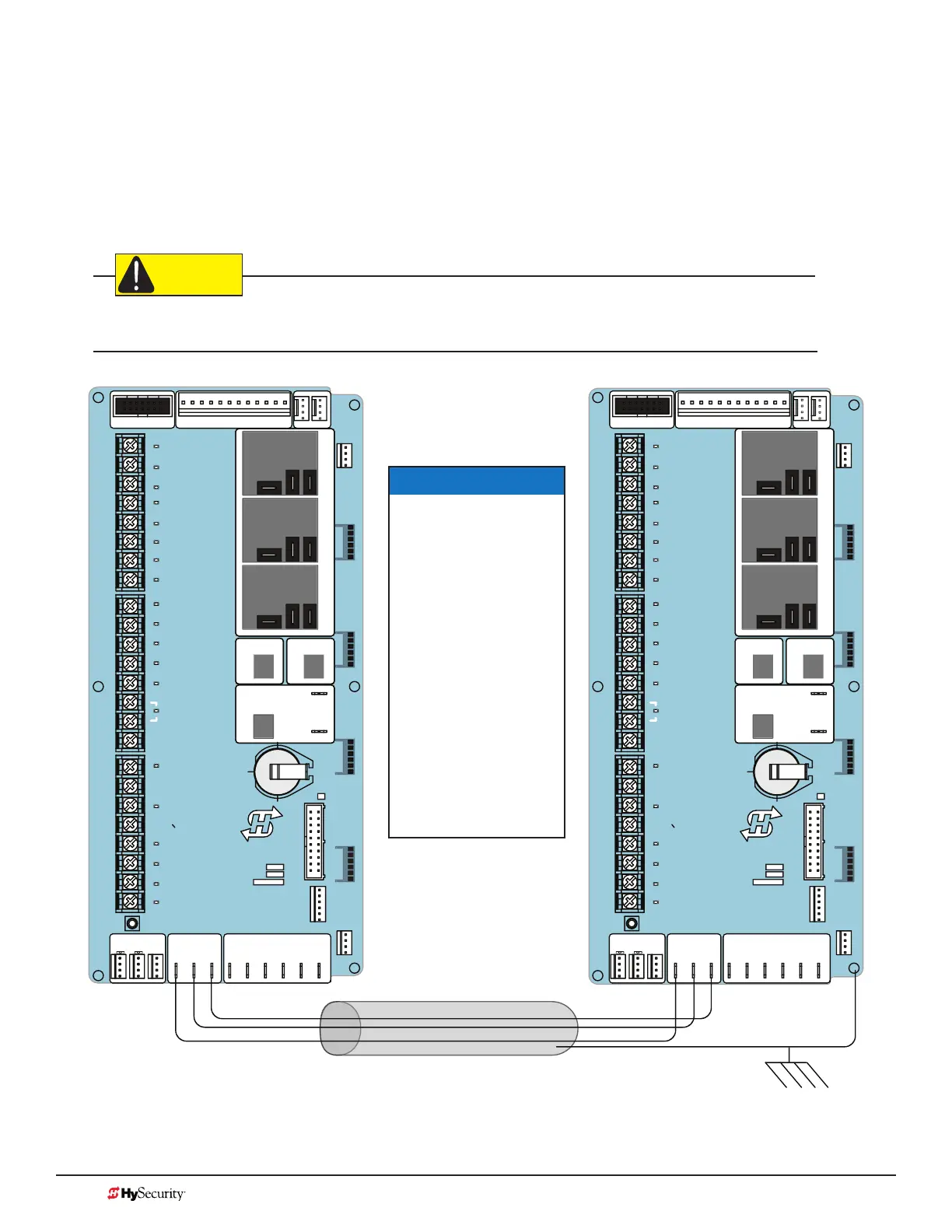
Dual Gate Wiring Connections
To connect an interlocked pair of gate operators, simply follow the steps below.
1. As shown in the Wire Diagram, connect a shielded communications cable to the DUAL GATE inputs in
each operator. The inputs are located near the base of the Smart Touch Controller. Be sure to connect
the wires in pairs to the same terminal ports (A-A, B-B, COM-COM) on both operators.
2. Attach a ring terminal to the shield wire and connect it to the Smart Touch Controller’s convenient
ground screw.
Connect the ground shield wire to only one operator, not both. Use only 18-20 gauge twisted and shielded wire.
To operate properly, both Smart Touch Controllers must be using the same software version.
STOP BUTTON
OPEN BUTTON
CLOSE BUTTON
REMOTE OPEN AND
RADIO CONTROL
OPEN/CLOSE
1
OPEN PARTIAL
INTERLOCK OPEN
TIME CLOCK OPEN
FREE EXIT DETECTOR
DISABLE EXIT DETECTOR
DISABLE CLOSE TIMER
INSIDE OBSTRUCTION
VEHICLE DETECTOR
OUTSIDE OBSTRUCTION
VEHICLE DETECTOR
SHADOW/RESET
VEHICLE DETECTOR
SENSOR 1
SENSOR
COM
DO NOT USE
SENSOR 2
DO NOT USE
SENSOR 3
DO NOT USE
CHARGER
AC LOSS
LOCK INTERLOCK
EMERG CLOSE
FIRE DEPT OPEN
2
3
4
5
6
7
8
9
10
11
12
14
15
16
17
18
19
20
21
22
23
24
Smart Touch Controller
LIMIT DUAL GATE
RADIO OPTIONS
DRIVE
POWER
RS485
MOTORUSER 1
USER 2
USER 3
VEHICLE DETECTORVEHICLE DETECTORVEHICLE DETECTOR
STOP/BUZZER
FREE
EXIT
INSIDE
OBSTR
OUTSIDE
OBSTR
SHADOW
RESET
WIEGAND
HySecurity
COM
NO
MX000585
VERSION
S/N
RS232
DISPLAY
VEHICLE DETECTOR
COMCOMAB
RPM
COMOPEN S1+24V +24V
STATUS
LED
STOP BUTTON
OPEN BUTTON
CLOSE BUTTON
REMOTE OPEN AND
RADIO CONTROL
OPEN/CLOSE
1
OPEN PARTIAL
INTERLOCK OPEN
TIME CLOCK OPEN
FREE EXIT DETECTOR
DISABLE EXIT DETECTOR
DISABLE CLOSE TIMER
INSIDE OBSTRUCTION
VEHICLE DETECTOR
OUTSIDE OBSTRUCTION
VEHICLE DETECTOR
SHADOW/RESET
VEHICLE DETECTOR
DO NOT USE
DO NOT USE
DO NOT USE
CHARGER
AC LOSS
LOCK INTERLOCK
EMERG CLOSE
FIRE DEPT OPEN
2
3
4
5
6
7
8
9
10
11
12
14
15
16
17
18
19
20
21
22
23
24
Smart Touch Controller
LIMIT DUAL GATE
RADIO OPTIONS
DRIVE
POWER
RS485
MOTORUSER 1
USER 2
USER 3
VEHICLE DETECTORVEHICLE DETECTORVEHICLE DETECTOR
STOP/BUZZER
FREE
EXIT
INSIDE
OBSTR
OUTSIDE
OBSTR
SHADOW
RESET
WIEGAND
HySecurity
COM
NO
MX000585
VERSION
S/N
RS232
DISPLAY
VEHICLE DETECTOR
COMCOMAB
RPM
COMOPEN S1+24V +24V
STATUS
LED
SENSOR 1
SENSOR
COM
SENSOR 2
SENSOR 3
Wire Diagram: Interlocked Pair of Operators wired to DUAL GATE Inputs
NOTICE
Use a 2-pair,
twisted, shielded
cable with one
pair of wires used
to connect A-A
and B-B terminals
between the two
boards. The other
pair will connect
the Common
terminals. The
shield should then
be grounded on
one end to one of
the operators.