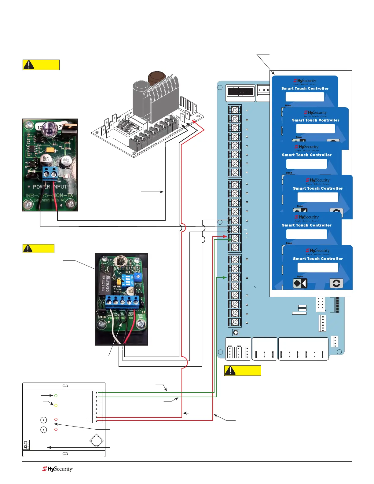
sMart touCh: Wireless edGe Gate link & Photo eye
The wiring diagram illustrates a wireless edge receiver and a photo eye connection. Refer to Photo Eye
Alignment Feature on page 104.
STOP BUTTON
OPEN BUTTON
CLOSE BUTTON
REMOTE OPEN AND
RADIO CONTROL
OPEN/CLOSE
1
OPEN PARTIAL
INTERLOCK OPEN
TIME CLOCK OPEN
FREE EXIT DETECTOR
DISABLE EXIT DETECTOR
DISABLE CLOSE TIMER
INSIDE OBSTRUCTION
VEHICLE DETECTOR
OUTSIDE OBSTRUCTION
VEHICLE DETECTOR
SHADOW/RESET
VEHICLE DETECTOR
SENSOR 1
SENSOR
COM
DO NOT USE
SENSOR 2
DO NOT USE
SENSOR 3
DO NOT USE
CHARGER
AC LOSS
LOCK INTERLOCK
EMERG CLOSE
FIRE DEPT OPEN
2
3
4
5
6
7
8
9
10
11
12
14
15
16
17
18
19
20
21
22
23
24
Smart Touch Controller
LIMIT DUAL GATE
RADIO OPTIONS
DRIVE
POWER
RS485
MOTOR USER 1
USER 2
USER 3
VEHICLE DETECTORVEHICLE DETECTORVEHICLE DETECTOR
STOP/BUZZER
FREE
EXIT
INSIDE
OBSTR
OUTSIDE
OBSTR
SHADOW
RESET
WIEGAND
HySecurity
COM
NO
MX000585
VERSION
S/N
RS232
DISPLAY
VEHICLE DETECTOR
COM COMA B
RPM
COMOPEN
S 1
+24V +24V
STATU S
LED
24V
A
C A
cce
s
s
or
y powe
r
+
24
V
D
C
EMX IRB MON Photo Eye
Receiver
Power Supply Board
EMX IRB MON Photo Eye
Transmitter
+24V
+24V
NC Relay to SENSOR
COMMON / NEG. to SENSOR COM
Jumper POWER INPUT - 24V to
COM in Receiver
COMMON / NEG. to SENSOR COM
To SENSOR COM
*Sensor wire (P/ NC) can
attach to any SENSOR
input.
MGL - RX20
+24V
NOTE: DIP switches must
be set as shown otherwise
the photo eye will not
operate correctly.
CAUTION
Set DIP Switches
1 = OFF
2 = OFF
3 = OFF
4 = ON
CAUTION
All external entrapment protection sensors must be
NC sensor outputs and wired to the SENSOR COM
terminal for monitoring and powering purposes.
The sensor becomes actively powered when the
gate operator's motor runs.
COM attaches to
SENSOR COM
POWER
STATUS
CH 1
CH 2
POWER
LEARN
OUTPUT
SELECT
CH 1 CH 2
COM
* P / NC
10K
COM
* P / NC
10K
+24V
Photo Eye
Transmitter
Green
Yellow
Miller Edge 2 Channel Wireless
Receiver (MGL - RX20)
CH 1 and CH 2 “LEARN” buttons. To identify and sync to one active transmitter, follow
manufacturer’s installation instructions. Use receivers & transmitters Version 1.02 or higher.
DIP switches for CH1 and CH2. Verify dip switch is set to “R” for each channel used. HySecurity uses NC
"Relay" sensors. Do NOT select "P" as the output. P = "Pulse" device.
MGL - RX20
S1 0
SENSOR #1 TYPE
S1 2 (EYE CLOSE)
SENSOR #1 TYPE
Congure Installer Menu items:
SENSOR 1, 2, & 3
S2 0
SENSOR #2 TYPE
S2 1 (NOT USED)
SENSOR #2 TYPE
S3 0
SENSOR #3 TYPE
S3 5 (EDGE OPEN)
SENSOR #3 TYPE
CAUTION
Connect all contact and non-contact sensors
to same power source. Example, Do NOT
connect photo eyes to +24VDC and gate
edges to +12VDC. Incompatible electricity
ow. A FAULT 2 will appear.
Antenna
MX3657-01 Rev. D ©2020
130 hysecurity.com | 800-321-9947 StrongArm Programming and Operations