sMart touCh: Wireless edGe, Wireless Gate link
A transmitter (MGL-TX20) and receiver (MGL-RX20)
are required.
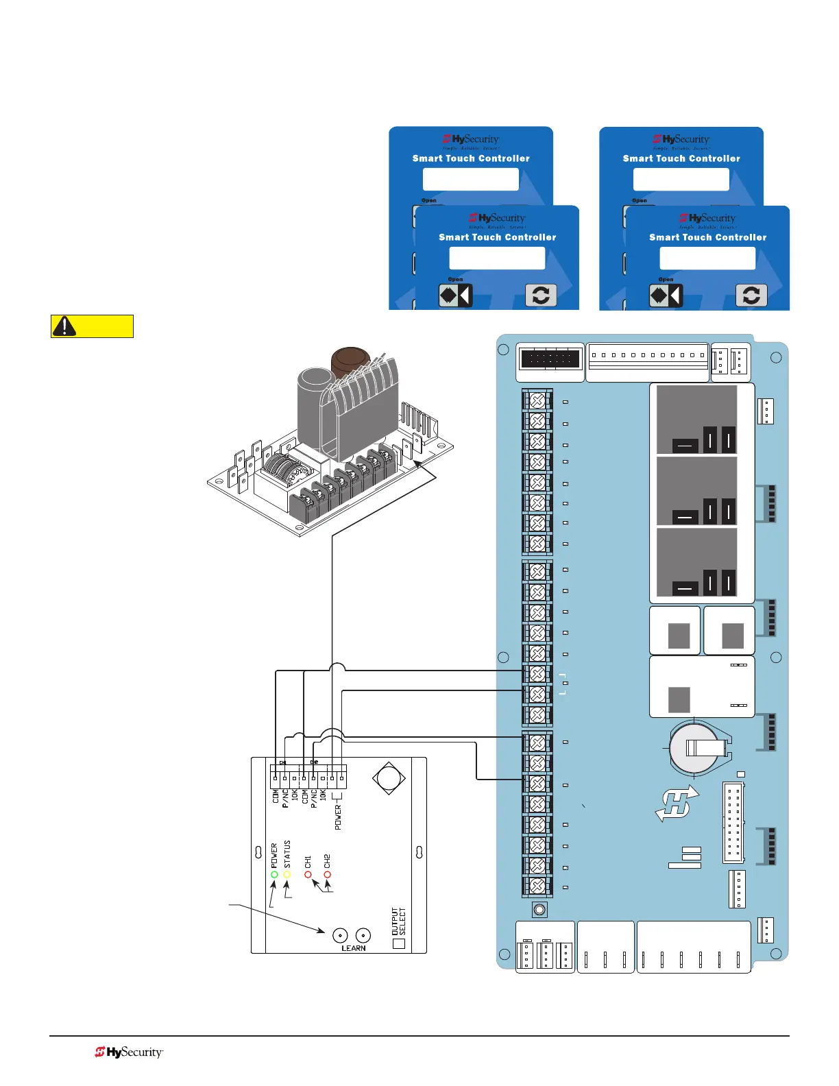
1. Turn OFF power.
2. Connect the wiring per the diagram shown.
3. Turn ON power and access the Installer
Menu.
4. Congure SENSOR setting accordingly (i.e.
Edge Open, Edge Close, or Edge Both).
Refer to table on page 29.
S2 0
SENSOR #2 TYPE
S2 5 (EDGE OPEN)
SENSOR #2 TYPE
S3 0
SENSOR #3 TYPE
S3 3 (EDGE CLOSE)
SENSOR #3 TYPE
Installer Menu showing SENSOR 2 set to EDGE OPEN (Option #5) and
SENSOR 3 set to EDGE CLOSE (Option #3)
STOP BUTTON
OPEN BUTTON
CLOSE BUTTON
REMOTE OPEN AND
RADIO CONTROL
OPEN/CLOSE
1
OPEN PARTIAL
INTERLOCK OPEN
TIME CLOCK OPEN
FREE EXIT DETECTOR
DISABLE EXIT DETECTOR
DISABLE CLOSE TIMER
INSIDE OBSTRUCTION
VEHICLE DETECTOR
OUTSIDE OBSTRUCTION
VEHICLE DETECTOR
SHADOW/RESET
VEHICLE DETECTOR
SENSOR 1
SENSOR
COM
DO NOT USE
SENSOR 2
DO NOT USE
SENSOR 3
DO NOT USE
CHARGER
AC LOSS
LOCK INTERLOCK
EMERG CLOSE
FIRE DEPT OPEN
2
3
4
5
6
7
8
9
10
11
12
14
15
16
17
18
19
20
21
22
23
24
Smart Touch Controller
LIMIT DUAL GATE
RADIO OPTIONS
DRIVE
POWER
RS485
MOTOR USER 1
USER 2
USER 3
VEHICLE DETECTORVEHICLE DETECTORVEHICLE DETECTOR
STOP/BUZZER
FREE
EXIT
INSIDE
OBSTR
OUTSIDE
OBSTR
SHADOW
RESET
WIEGAND
HySecurity
COM
NO
MX000585
VERSION
S/N
RS232
DISPLAY
VEHICLE DETECTOR
COM COMA B
RPM
COMOPEN
S 1
+24V +24V
STATU S
LED
24V AC Acce
s
sory power
+
24
V
D
C
COMMON
Wireless Edge Link (Receiver)
MGL - RX20
Signal received from battery-powered
Connect either channels
output (P/NC wire) to
SENSOR 1, 2, or 3.
Green
Yellow
Red (Channel 1 &
Channel 2)
Power Supply Board
CAUTION
All external entrapment protection
sensors must be NC sensor outputs
and wired to the SENSOR COM
terminal for monitoring and powering
purposes. The sensor becomes actively
powered when the gate operator's
motor runs.
NOTE: In bi-parting swing gates,
CH1 and CH2 may be programmed
to the same SENSOR # TYPE on
one controller, but each CH must
be connected to separate SENSOR
inputs. Always make sure that a gate
edge is installed on each bi-parting
swing gate.
NOTE: Use Miller Gate Edges
that have a wire marked with Blue
Tape. The Blue Tape indicates a
resistor is built in. Use receivers
and transmitters, labeled Version
1.02 or higher.
Miller Edge LEARN mode. Press
the LEARN button on the Receiver
for 2 seconds until the amber light
blinks continuously. Press the Edge
or Test button on the Transmitter
to complete the LEARN mode
process and sync the receiver and
transmitter.
Be aware. Issues with radio interference
cause false trips. Placing the antenna
high and reducing environmental
“noise” is critical to proper wireless
transmission. Avoid placing the
receiver sets within 100 feet of each
other as crosstalk may occur.
MX3657-01 Rev. D ©2020
128 hysecurity.com | 800-321-9947 StrongArm Programming and Operations