8000 SRM 1197 General
WARNING
The battery is h
eavy. Use appropriate lifting
equipment to av
oid personal injury.
3. Remove the batt
ery from the lift truck.
WARNING
The truck must be kept level while raising.
4. Raise the lift truck and position solid, one-piece
hardwood blocks or an approved lift truck frame
stand under the frame. The truck must be kept
level while raising. Frequently reposition jack
stands or blocks under the frame while raising as
a safety precaution in case of equipment failure.
DO NOT raise any point of the frame 50 mm
(2 in.) more than any other point of the frame.
MANUAL LOWERING VALVE
N30-35ZDR and N35-40-45ZR
WARNING
Allow no on under or near the lift mechanism
or load during the manual lowering procedure.
Always verify that there are no obstructions
beneath the lift mechanism or load before at-
tempting to lower the mast manually.
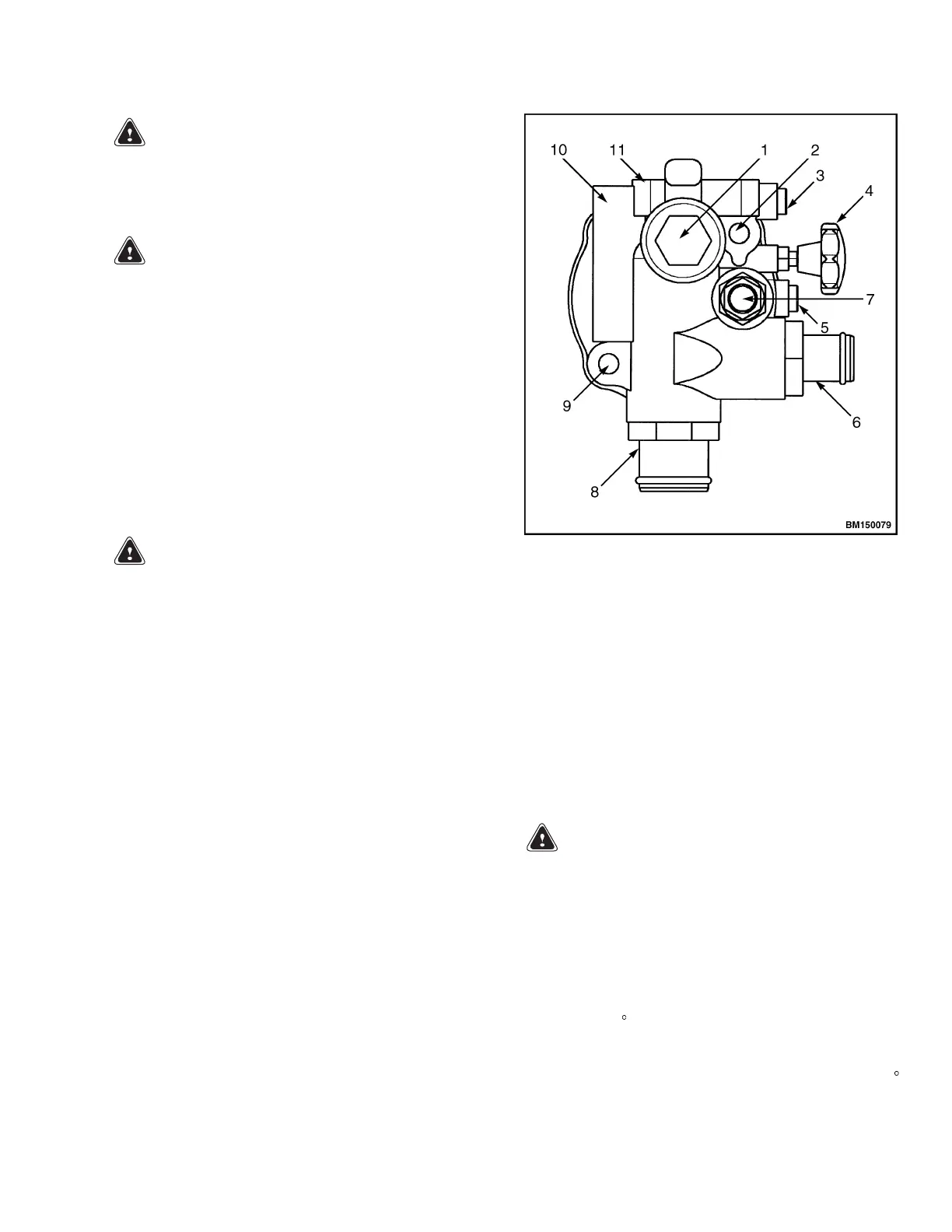
The manual lowering valve is located on the main
lift pump manifold beside the hydraulic tank. The
manual lowering valve can be opened by turning the
valve knob counterclockwise to relieve pressure from
the hydraulic system. This can be used to manu-
ally lower the mast in case of malfunction or to re-
lieve pressure from the system before servicing the
hydraulics. If the mast leaks down during operation,
lower the mast and check that the knob is completely
closed (turn clockwise). Always close the manual
lowering valve after use. See Figure 6.
1. LOWERING CONTROL VALVE
2. UPPER MOUNTING HOLE
3. M2 TEST PORT
4. MANUAL LOWERING VALVE KNOB
5. M1 TEST PORT
6. RETURN FITTING
7. RELIEF VALVE
8. SUPPLY FITTING
9. LOWER MOUNTING HOLE
10. OVERRUN CHECK VALVE
11. PRESSURE FLANGE
Figure 6. Pump (Valve Manifold)
N30ZDRS and N35-40ZRS
WARNING
Allow no on under or near the lift mechanism
or load during the manual lowering procedure.
Always verify that there are no obstructions
beneath the lift mechanism or load before at-
tempting to lower the mast manually.
Manual lowering is accomplished by pushing in the
manual lowering valve knob and turning it counter-
clockwise 180
until the knob pops back out. See Fig-
ure 7. This will open the valve and the mast will be-
gin lowering at a controlled rate. Push the load hold-
ing check valve knob in and turn it clockwise 180
until it pops back out to close. See Figure 7.
7

 Loading...