8000 SRM 1197 General
Drive Unit Compartment Door
Completely loosen the two socket head capscrews se-
curing the drive unit compartment door closed. The
screws are spring loaded and retained to the door
by clips. Pull the door open on its hinges. To close,
push the door closed and start both socket head cap-
screws loosely into the mounting holes. When both
screws are started, verify that the door seats prop-
erly against the frame and tighten the screws.
Caster Wheel Cover
Remove the socket head capscrews on top of the
caster wheel cover and lift cover from the clips se-
curing it to the frame.
To replace, fit the bottom of the cover into the clips
inside the opening and slide the cover into place. In-
stall two socket head capscrews to secure the top of
the cover in place.
DISCHARGING THE CAPACITORS
WARNING
Capacitors inside the controllers can hold
an electrical charge after the battery is dis-
connected. Discharge the capacitors before
servicing the electrical system to prevent in-
jury or electronic damage.
1. Move the lift truck to a safe, level area and com-
pletely lower the mast. Turn the key switch to
the OFF position and attach a DO NOT OPER-
ATE tag to the control handle. Block the drive
wheel to prevent unexpected movement.
2. Disconnect the battery power cable connector
from the truck connector located on the right side
of the frame. Pull the battery cable connector
handle to separate the battery connector from
the truck connector.
3. Remove the operator compartment cover.
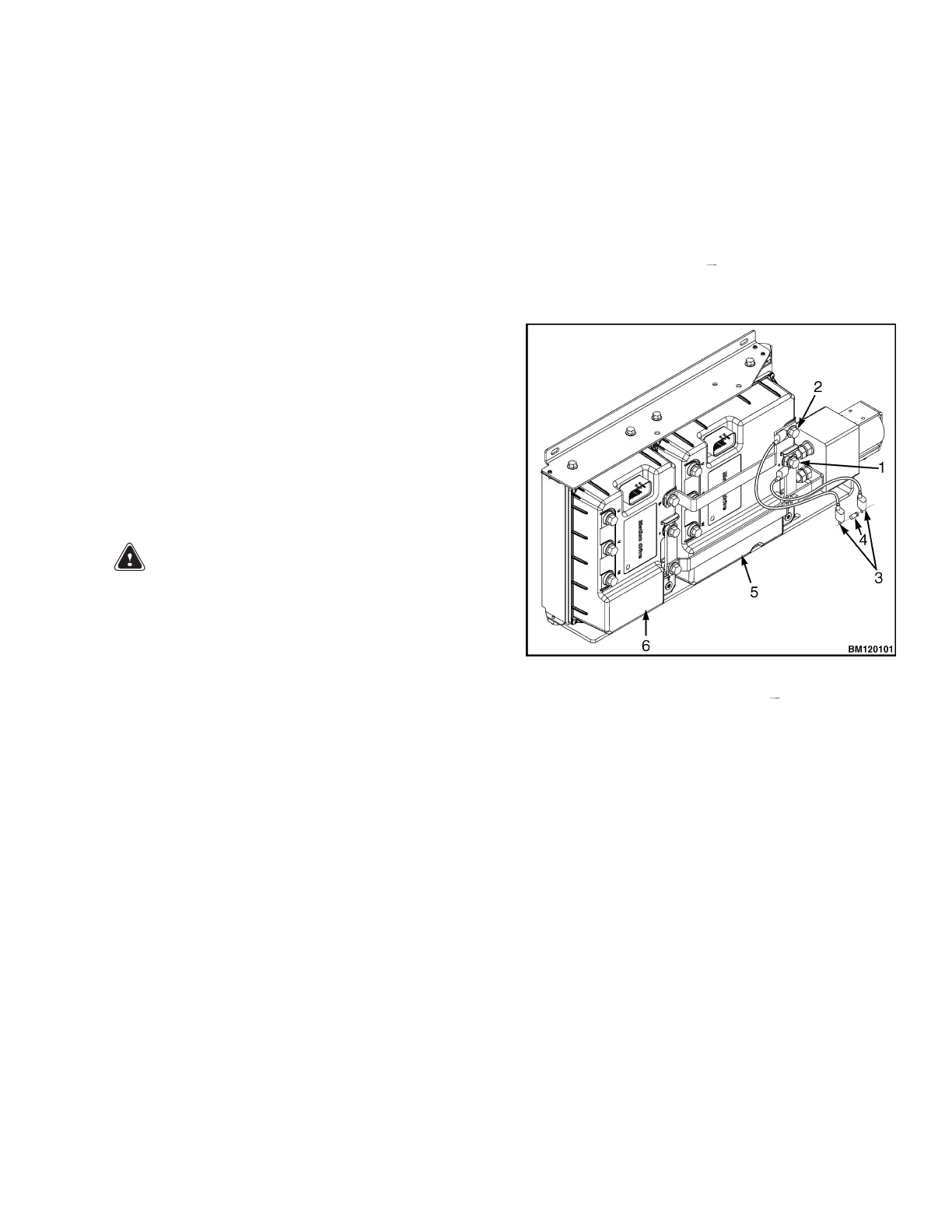
4. Discharge the capacitor in the controllers by
connecting a 200-ohm, 2-watt resistor across the
controller B+ and B
terminals of the motor
controller for 10 seconds. Remove the resistor
after discharging the capacitors. See Figure 3.
1. POSITIVE CONNECTION (B+)
2. NEGATIVE CONNECTIONS (B )
3. INSULATED JUMPER WIRES
4. 200-OHM, 2-WATT RESISTOR
5. PUMP MOTOR CONTROLLER
6. TRACTION MOTOR CONTROLLER
Figure 3. Discharging the Capacitors
3