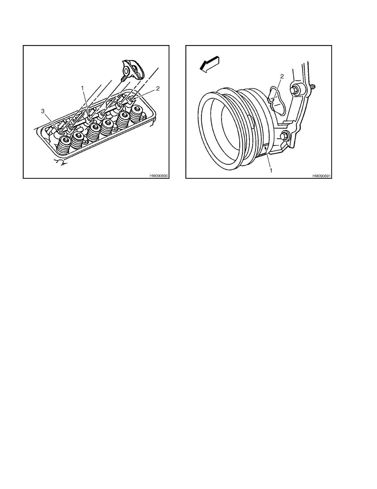
1. BOLT AT LOCATION 1
2. BOLT AT LOCATION 2
3. BOLT AT LOCATION 3
Figure 25. Install Valve Rocker Arm Assemblies
11.
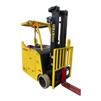
Rotate crankshaft balancer to position crank-
shaft balancer alignment mark 57 to 63 degrees
clockwise or counterclockwise from engine front
cover alignment tab. See Figure 26.
NOTE: Once valve rocker arm assemblies are in-
stalled and properly torqued, no additional valve
lash adjustment is required.
1. CRANKSHAFT BALANCER ALIGNMENT MARK
2. ENGINE FRONT COVER ALIGNMENT TAB
Figure 26. Rotate Crankshaft Balancer
12.
Tighten valve rocker arm bolts to
30 N•m (22 lbf ft). See Figure 24.
13.
Use new gasket and install valve covers. Install
new grommets on capscrews and install cap-
screws into valve covers. Tighten capscrews to
12 N•m (107 lbf in). See Figure 27.
Cylinder Head Repair 0600 SRM 1251
16