3
Before Use
Instructions
To ensure optimum performance and reliability of the
repeater, please read the following instructions carefully.
Operation Environment
The repeater must be installed in a dry and well-
ventilated place with ambient temperature of -30℃ to
+60℃ and relative humidity of not more than 95%.
Voltage Check
Check whether the input voltage is within the operating
voltage of the repeater (DC power supply: 13.6V±15%;
AC power supply: 90V to 264V).
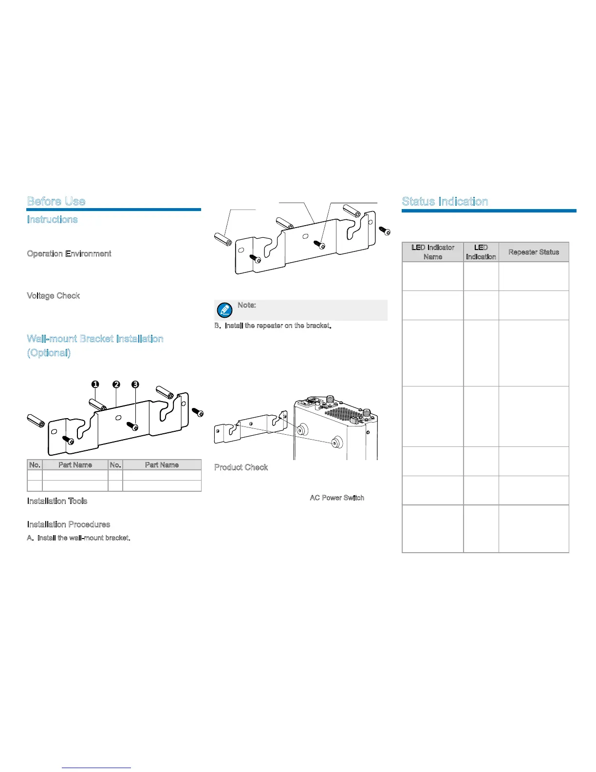
Wall-mount Bracket Installation
(Optional)
If you need to install the repeater on the wall, please
contact your dealer to purchase a wall-mount bracket.
1
2 3
No. Part Name No. Part Name
1 Plastic Wall Anchor 3 Self-tapping Screw
2 Wall-mount Bracket / /
Installation Tools
An electric drill and a T10 torx screwdriver.
Installation Procedures
A. Install the wall-mount bracket.
1. Drill three holes into the wall, with each hole aligned
with those of the wall-mount bracket.
2. Put the plastic wall anchor into the drilled holes. Skip
this step if the wall is not a concrete wall.
3. Use three ST4X16 self-tapping screws to fasten the
bracket on the wall.
Note: Make sure the wall can support the
repeater’s weight before drilling.
B. Install the repeater on the bracket.
1. Align the screws on the upper side of the repeater
with the notches of the bracket and mount the
repeater onto the bracket, as shown in the figure
below;
2. Move the repeater side to side slightly to ensure the
screws fit into the bottom of the notch.
Product Check
Check whether the repeater works properly by observing
the seven LED indicators in the front panel after the
repeater is powered on via the
AC Power Switch.
Wall-mount
Bracket
Self-
tapping Screw
Plastic Wall
Anchor
Status Indication
The LED indicators on the front panel indicate the
following repeating status:
LED Indicator
Name
LED
Indication
Repeater Status
Digital Mode LED
Indicator
Blue
The repeater is
operating in digital
mode.
Analog Mode LED
Indicator
Yellow
The repeater is
operating in analog
mode.
Slot A TX LED
Indicator
Red
●
Analog mode:
The repeater is
transmitting.
●
Digital mode:
The repeater is
transmitting in Slot
A.
Slot A RX LED
Indicator
Green
●
Analog mode:
The repeater is
receiving.
●
Digital mode:
The repeater is
receiving
in Slot A.
Slot B TX LED
Indicator
Red
Digital mode:
The repeater is
transmitting in Slot B.
Slot B RX LED
Indicator
Green
Digital Mode: The
repeater is receiving
in Slot B.
Alarm LED
Indicator
Red
Alarm occurs. The
alarm LED indicator
will remain red
until all alarms are
eliminated.

 Loading...