DSP-OHMNI Instruction Manual I-GARD
9
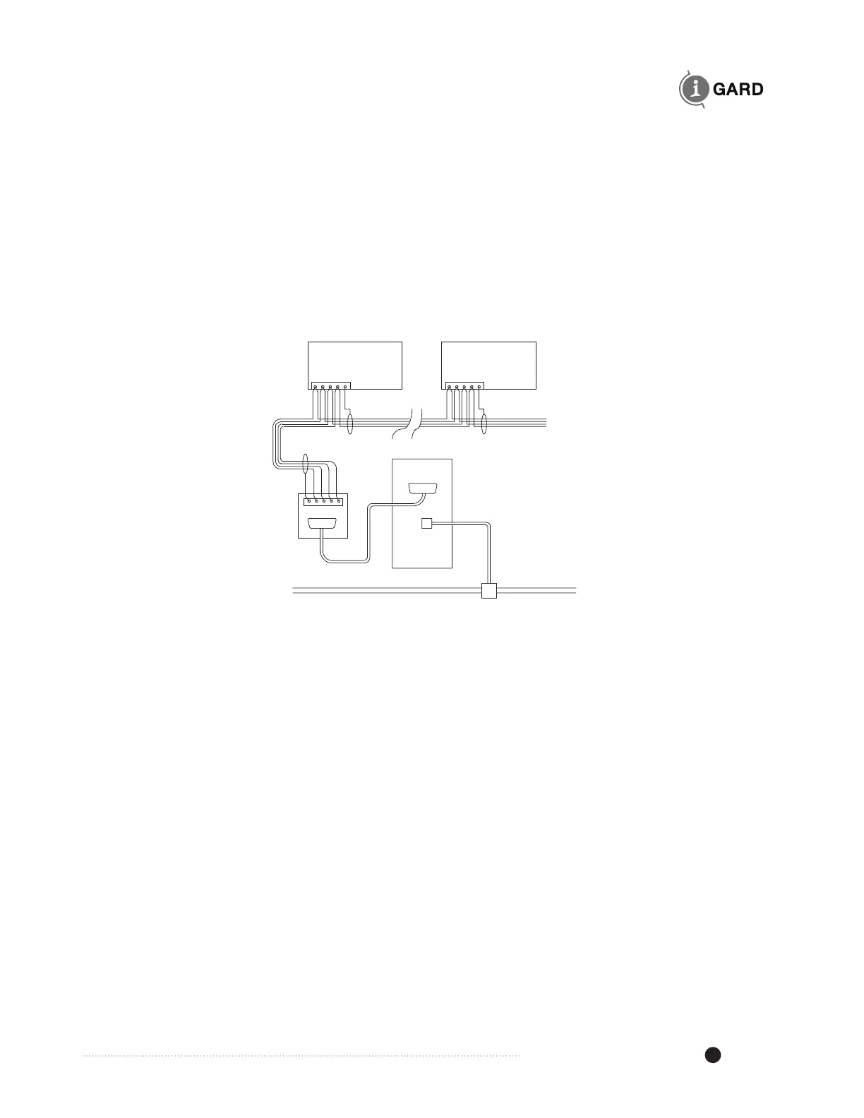
The RS-485 cable shield should be grounded at the ground terminal provided on the 5–pin jack as shown
in Figure 4.4, which shows a typical installation with a local computer and LAN.
Communications may be supported as a node in an existing MODBUS network or may be connected
through a standard RS-485 to RS-232 converter to a PC with supporting software.
The Alarm contacts are available at the DSP-DPS as a Form C type and should be connected to operate
a horn or other means to alert an operator to the fact that a fault has occurred on the HRG system. The
contacts are rated at 10A, 240VAC Resistive.
Figure 4.4 Typical 4-wire Communications Connection
Communications wiring may be 2-wire or 4-wire but must use shielded cable with low capacitance. Wire
lengths up to 2000 metres can generally be used without the need for termination resistors.
Figures 4.4 and 4.5 show typical RS-485 arrangements with a RS-485/RS-232 converter and a host PC
connected to a LAN.
DSP-DM
(01)
DSP-DM
(nn)
RS-232
COM Port
Computer
Host
Other 485 Devices
Network
TCP/IP