DSP-OHMNI Instruction Manual I-GARD
5
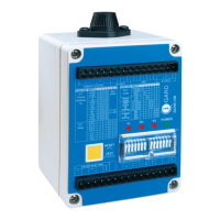
DDAI and OHMNI-PM devices are available for continuous currents of 1 ampere to 10 amperes for
most systems. For further information regarding the use of these devices refer to:
Instruction Manual Type DDAI Artificial Neutrals C-430EM
Instruction Manual Type DDR2 Alarm Resistor Units C-440EM
Instruction Manual Type OHMNI-PM Neutral Grounding Resistors C-450EM
3 INSTALLATION
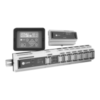
A typical installation will include for each power source (transformer/generator) 1 DSP-DM, 1 DSP-DPS,
1 DSP-DSM and a number of DSP-DFM Feeder Modules as required with 1 for each branch protected.
Additionally there will be a DSP-PM pulsing resistor to ground the system. A voltage-sensing resistor DDR2
is required for the DSP-DSM input, as well as one current sensor for each DSP-DFM for current detection.
See Table 3.1 for typical requirements.
TABLE 3.1 SYSTEM MODULE REQUIREMENTS
Catalog Number Description No Required/System
DSP-DM Display Module 1
DSP-DPS Power Supply 1
DSP-DSM System Voltage Module 1
DSP-DFM Feeder Module As required 1/ Circuit
OHMNI-PM Pulse Equipped Resistor 1
DDR2 Voltage Sensing Resistor 1
DDAI Artificial Neutral Required only for delta system
T Toroidal Current Sensor 1/Feeder Module
TABLE 3.2. STANDARD RIBBON CABLES
Length Function Catalog Number
365cm (12ft) DSP-DM to DSP-DPS DRC-365
150cm (5ft) DSP-DM to DSP-DPS DRC-150
5cm (2 in.) Module to Module connection RC-3
30cm (12 in.) Module to Module connection RC-30
DSP modules are mounted on a 35mm DIN Rail generally located at the rear wall of a switchgear
compartment. They should be mounted side by side and connected with 20-conductor ribbon cable in a
daisy chain configuration. This applies to the DSP-DPS, DSP-DSM and DSP-DFM modules only.