DSP-OHMNI Instruction Manual I-GARD
31
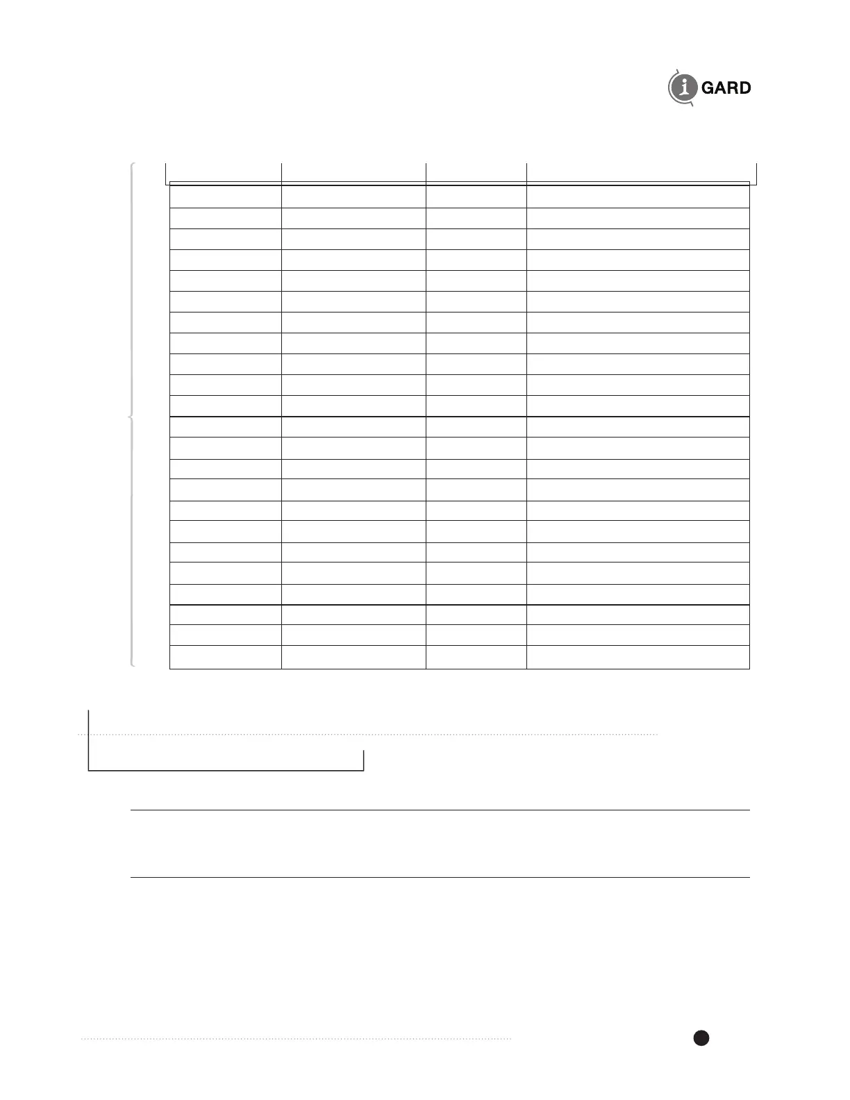
TABLE 13.8 SYSTEM FUNCTION REGISTERS
Register Function Format Description
40151 System IG current 0x00nn nn = 0-100% Total System
leakage current I
Gt
40152 System Status 0x00nn Nn
01 = Normal no fault
10 = A phase low
20 = B phase low
40 = C phase low
70 = All phases low
82 = A phase faulted
84 = B phase faulted
88 = C phase faulted
40153 Pulse setup 0x00nn nn lower byte is a composite
byte upper nibble is Mode of
operation while lower nibble
of nn is pulse frequency 0 – 9.
nn
0n = Normal, interlock OFF
1n = Inverted, interlock OFF
2n = Normal , interlock ON
3n = Inverted, interlock ON
40154 Pulse Status 0x000n n
0=Pulsing OFF
1=Pulsing ON
14 SPECIFICATIONS
14.1 Power Requirements DSP-DPS
100-240V, 50/60Hz or DC, 25VA
14.2 Maximum Ratings DSP-DPS
Control voltage 250V AC/DC
Dielectric
Relay contacts to chassis 1500V rms. for 1 minute
Control terminals to chassis 1500V rms. for 1 minute
DC output maximum rating 22W max for +5, +12 and 12V supplies