I-GARD DSP-OHMNI Instruction Manual
10
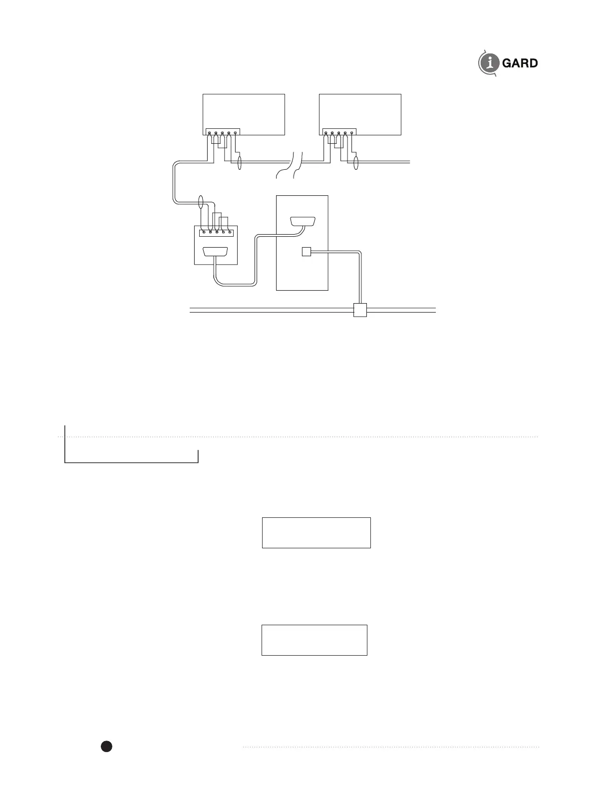
Figure 4.5 Alternative two-wire connection for RS-485
For Fault location the DSP system is equipped with Pulse modulation for the ground current to identify the
fault more readily. Pulse current is provided at the DSP-DPS (+) and (-) terminals, which may be directly
connected to the Pulse Relay in the DSP-PM grounding Resistor. It is important to observe the polarity of
the connection. This 12V wiring need not be shielded but should be 14 AWG switchboard wire for durability.
5 DISPLAY
Following successful installation of the DSP system and connection of the control voltage, the DSP-DM
display module should indicate a Green NORMAL light and the screen should show the following message.
I-GARD
HRG SYSTEM OK
Figure 5.1 Home Screen
If the following screen appears and the local Alarm sounds, then most likely the DDR2 resistor is not
energized or connected.
3 PHASES LOST
CHECK DDR2 FUSE
Figure 5.2 Alarm Screen
DSP-DM
(01)
DSP-DM
(nn)
RS-485 to RS232
Converter
RS-232
COM Port
Computer
Host
Other 485 Devices
Network
TCP/IP
Tx+Tx-Rx+Rx-
Tx+ Tx-Rx+Rx- G
G
Tx+Tx-Rx+Rx- G