I-GARD DSP-OHMNI Instruction Manual
2
TABLE OF FIGURES
Figure 4.1 a) Typical One-Line Installation - Unit Substation b) System Module DSP-DSM Wiring 7
Figure 4.1 c) Power Supply DSP-DPS wiring 7
Figure 4.2 Preferred Feeder Module DSP-DFM Wiring 8
Figure 4.3 Alternative Sensor Wiring 8
Figure 4.4 Typical 4-wire Communications Connection 9
Figure 4.5 Alternative two-wire connection for RS-485 10
Figure 5.1 Home Screen 10
Figure 5.2 Alarm Screen 10
Figure 6.1 Communications Set-up 11
Figure 6.2 Communications Set-up 11
Figure 6.3 Grounding Resistor Set-up 12
Figure 6.4 Feeder Module Set-up 12
Figure 6.5 I/D Check indication 13
Figure 6.6 Feeder Module Set-up 14
Figure 6.7 a) Feeder Module Successful b) Set-up Not Successful 14
Figure 6.8 a) DSP-DM allows further Feeder Module set-up b) If previous set-up had not been successful 14
Figure 6.9 Pulse Set-up Request 15
Figure 6.10 Pulse Mode Set-up 15
Figure 6.11 Typical Examples of Pulse Circuit Connection 16
Figure 6.12 Alarm relay Setup 17
Figure 6.13 Alarm relay Options 17
Figure 6.14 Save Screen 18
Figure 6.15 Self-Test Prompt 18
Figure 7.1 Normal Home Screen 18
Figure 7.2 System leakage current l
G
19
Figure 7.3 Feeder Current I
Gf
19
Figure 7.4 Trip Defeated 19
Figure 7.5 Pulse Control 20
Figure 7.6 New Home screen indicates Pulsing ON 20
Figure 8.1 Alarm Screen 21
Figure 8.2 Bus Fault 22
Figure 9.1 System-Test Prompt 22
Figure 9.2 Prompt for Feeder Test 22
Figure 9.3 Feeder Module Test 23
Figure 9.4 Test Result 23
Figure 10.1 Event Notification 23
Figure 10.2 Momentary Feeder Fault Example 23
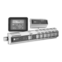
Figure 15.1 DIN Rail Mounted Modules 33
Figure 15.2 DSP-DM Display Module with cut-out detail 34
Figure 15.3 DSP-DPS Power Supply Connections 35
Figure 15.4 DSP-DSM System Module Connection 35
Figure 15.5 DSP-DFM Feeder Module Connection 35
Figure 15.6 DSP-DM Display Module Connections 36