<Encoder Resolution> See below for the resolution of encoders mounted on the connectable actuators.
Actuator Type Encoder Resolution
RCP2 to 5 All Types 800 pulse/rev
Pulse Motor
RCP6 All Types 8192 pulse/rev
Incremental Encoder 800 pulse/rev
RCA
Battery-less Absolute Encoder 16383 pulse/rev
RCA2-□□□N(A) 1048 pulse/rev
RCA2
Except for RCA2-□□□N(A) 800 pulse/rev
RA1L ‧ SA1L ‧ SA4L ‧ SM4L 715 pulse/30.03 mm
RA2L ‧ SA2L ‧ SA5L ‧ SM5L 855 pulse/35.91 mm
Servo Motor
RCL
RA3L ‧ SA3L ‧ SA6L ‧ SM6L 1145 pulse/48.09 mm
RA1D ‧ GRSN 400 pulse/rev
Brushless DC
Motor
RCD
RA1DA ‧ GRSNA 480 pulse/rev
● Specifications of DeviceNet Interface
Item Specification
Communication Protocol DeviceNet 2.0, Group 2 Dedicated Server, Network-Powered Insulation Node
Baud Rate, Communication System Automatically follows the master, Master-Slave System (Polling)
Number of Occupied Channels,
Number of Occupied Node
MAX. 72CH (Input, Output), 1 node
Baud Rate
Max. Network
Length
Total Branch Line
Length
Max. Branch Line
Length
500kbps 100m 39m
250kbps 250m 78m
Communication Cable Length
(Note 1)
125kbps 500m 156m
6m
Communications Cable Use the dedicated cable.
Connector
(Note 2)
MSTB2.5/5-GF-5.08 AU (Manufactured by PHOENIX CONTACT or equivalent)
Communication Power Supply,
Consumption Current
24V DC (Supplied from DeviceNet), 60mA
Note 1 For T branch communication, refer to the Instruction Manuals for the master unit and programmable controller (PLC)
to be mounted.
Note 2 The cable-side connector is a standard accessory. [Refer to Product Check 1.Parts]
● Specifications of CC-Link Interface
Item Specification
Communication Protocol CC-Link ver 1.10 or ver 2.00
Station Type Remote Device Station (MAX. four stations occupied)
Baud Rate, Communication System 10M/5M/2.5M/625k/156kbps, Broadcast Polling System
Number of Connectable Stations MAX. 63 stations
Baud Rate (bps) 10M 5M 2.5M 625k 156k
Communication Cable Length
(Note 1)
Total Cable Length (m) 100 160 400 900 1200
Communications Cable Use the dedicated cable.
Connector
(Note 2)
MSTB2.5/5-GF-5.08 AU (Manufactured by PHOENIX CONTACT or equivalent)
Note 1 For T branch communication, refer to the Instruction Manuals for the master unit and programmable PLC to be mounted.
Note 2 The cable-side connector is a standard accessory. [Refer to Product Check 1.Parts]
● Specifications of PROFIBUS-DP Interface
Item Specification
Communication Protocol PROFIBUS-DP
Baud Rate, Communication System Automatically follows the master, Hybrid System (Master-Slave System or Token
Passing System)
Occupied Domain MAX. 144 byte (Input, Output)
Number of Connectable Stations MAX. 32 stations/segments available up to 126 stations with repeater
MAX. Total Network Baud Rate Cable Type
100m 3,000/6,000/12,000kbps
200m 1,500kbps
400m 500kbps
1000m 187.5kbps
Communication Cable Length
(Note 2)
1200m 9.6/19.2/93.75kbps
Type A Cable
Communications Cable STP cable AWG18
Connector
(Note 1)
9-pin female D-sub Connector
Transmission Path Format Bus/Tree/Star
Note 1 Please prepare a 9-pin male D-sub connector for the cable-end connector.
● Specifications of CompoNet Interface
Item Specification
Communication System CompoNet dedicated protocol
Communication Type, Baud Rate Remote I/O communication, Automatically follows the master
Communication Cable Length Follows CompoNet specifications
Slave Type Word-Mixed Slave
Available Node Addresses for Setting 0 to 63 (Setting conducted on controller parameter)
Communications Cable
(To be prepared by User)
Round Cable (JIS C3306, VCTF2-core)
Flat cable I (with no sheathed)
Flat cable II (sheathed)
Connector (Controller Side) XW7D-PB4-R (Manufactured by OMRON or equivalent)
● Specifications of EtherNet/IP Interface
Item Specification
Communication Protocol IEC61158 (IEEE802.3)
Baud Rate 10BASE-T/100BASE-T (Autonegotiation setting is recommended)
Communication Cable Length
Follows EtherNet/IP specifications
(Distance between hub and each node: 100m max.)
Number of Connection Master Unit
Available Node Addresses for Setting 0.0.0.0 to 255.255.255.255
Communications Cable
(To be prepared by User)
Category 5 or more
(Double shielded cable braided with aluminum foil recommended)
Connector RJ45 Connector × 1pc
● Specifications of EtherCAT Interface
Item Specification
Communication Protocol IEC61158 type 12
Physical Layer 100Base-TX (IEEE802.3)
Baud Rate Automatically follows the master
Communication Cable Length Follows EtherCAT® specifications (Distance between each node: 100m max.)
Slave Type I/O slave
Available Node Addresses for Setting 0 to 127
Communications Cable
(To be prepared by User)
Category 5 or more
(Double shielded cable braided with aluminum foil recommended)
Connector RJ45 Connector × 2pcs (Input × 1, Output × 1)
Connect Daisy chain only
● Specifications of PROFINET IO Interface
Item Specification
Communication Protocol IEC61158 (IEEE802.3), IEC61784
Baud Rate 100Mbps
Communication Cable Length Distance between each segment: 100m Max.
Number of Connection Master Unit
Available Node Addresses for Setting 0.0.0.0 to 255.255.255.255
Communications Cable
(To be prepared by User)
Category 5 or more
(Double shielded cable braided with aluminum foil recommended)
Connector RJ45 Connector × 1pc
GSDML File Version Ver 2.3
● Specifications of CC-Link IE Field Interface
Item Specification
Communication Protocol, Baud Rate Conforms to IEEE802.3ab (1000BASE-T), 1Gbps
Communication System Token Passing System
Communication Cable Length Distance between each segment: 100m Max.
Max. Number of Connected Units,
Max. Networks
254units (Total of master and slave stations), 239networks
Communications Cable
(To be prepared by User)
Category 5e or more
(Double shielded cable braided with aluminum foil recommended)
Connector RJ45 Connector × 2pcs
Cyclic Communication
RX (Slave → Master): 16384bits, RY (Master → Slave): 16384bits
RWr (Slave → Master): 8192words, RWw (Master → Slave): 8192words
●
Refer to SSCNET
Ⅲ
/H interface specifications, SSCNET
Ⅲ
/H Applicable for Controller Instruction Manual (ME0352).
● Refer to MECHATROLINK-Ⅲ interface specifications,
MECHATROLINK-Ⅲ Applicable for Controller
Instruction Manual (ME0317).
● Refer to EtherCAT Motion interface specifications, EtherCAT Motion Applicable for Controller Instruction
Manual (ME0367).
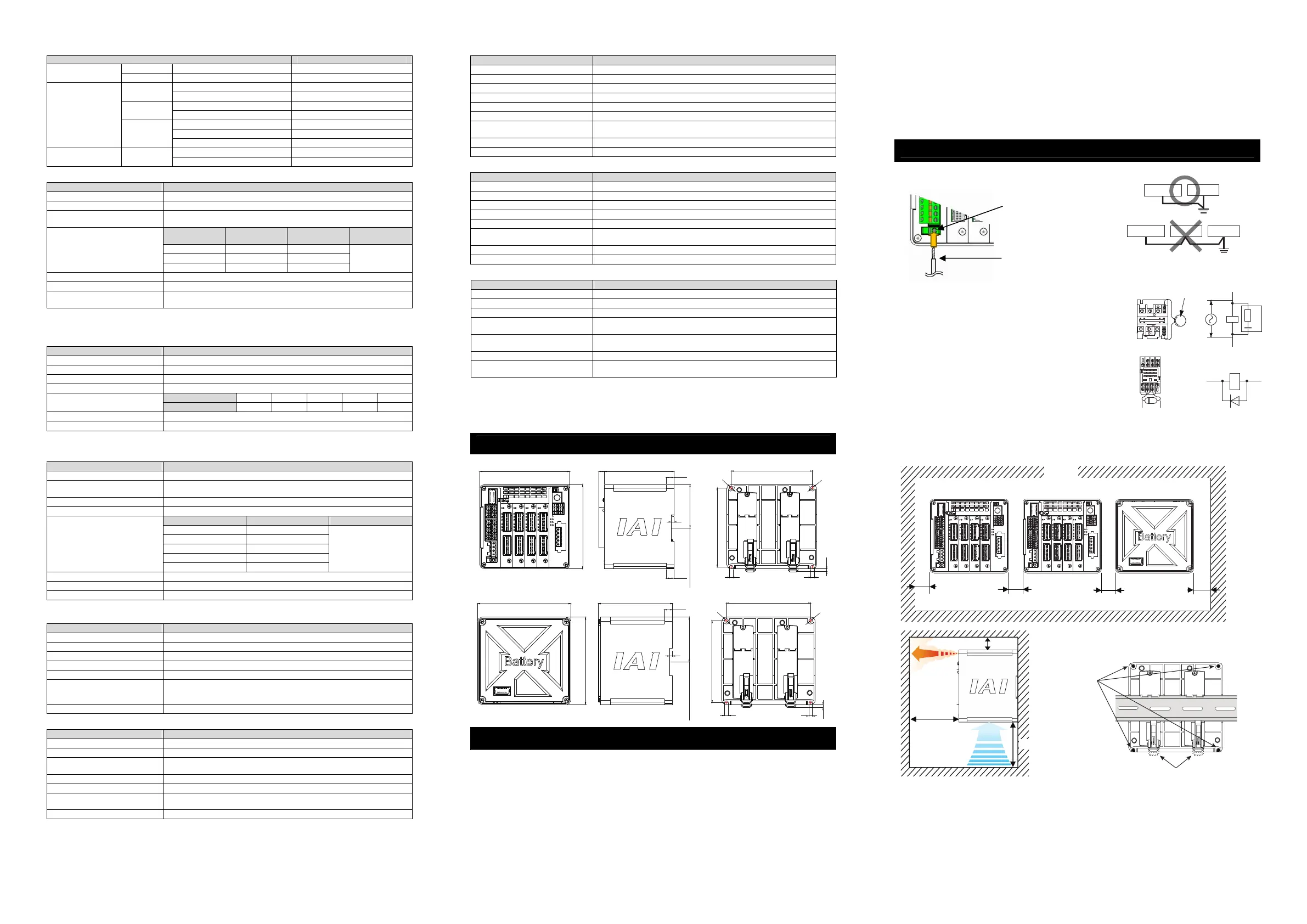
External Dimensions
Controller Main Body
123
115
957.5
59 from DIN rail center
10.5
10.5
4
111
108
φ5
5
5
(4)
φ5
Absolute Battery Box
111
108
φ
5
φ5
5
5
(4)
123
115
59 from DIN rail center
10.5
4
98
Installation Environment
This product is capable for use in the environment of pollution degree 2
*1
or equivalent.
* 1 Pollution Degree 2 : Environment that may cause non-conductive pollution or transient conductive
pollution by frost (IEC60664-1).
1. Installation Environment
Do not use this product in the following environment.
Location where the surrounding air temperature
exceeds the range of 0 to 40C
Location where condensation occurs due to abrupt
temperature changes
Location where relative humidity exceeds 85%RH
Location exposed to corrosive gases or combustible
gases
Location exposed to significant amount of dust, salt or
iron powder
Location subject to direct vibration or impact
Location exposed to direct sunlight
Location where the product may come in contact with
water, oil or chemical droplets
Environment that blocks the air vent
[Refer to Installation and Noise Elimination]
When using the product in any of the locations specified below, provide a sufficient shield.
Location subject to electrostatic noise
Location where high electrical or magnetic field is present
Location with the mains or power lines passing nearby
2. Storage and Preservation Environment
Storage and preservation environment follows the installation environment. Especially in a long-term storage,
consider to avoid condensation of surrounding air.
Unless specially specified, moisture absorbency protection is not included in the package when the machine is
delivered. In the case that the machine is to be stored in an environment where dew condensation is anticipated, take
the condensation preventive measures from outside of the entire package, or directly after opening the package.
Installation and Noise Elimination
1. Noise Elimination Grounding (Frame Ground)
2. Precautions regarding wiring method
1) Wire is to be twisted for the 24V DC power supply.
2) Separate the signal and encoder lines from the power supply and power
lines.
3. Noise Sources and Elimination
Carry out noise elimination measures for electrical devices on the same
power path and in the same equipment.
The following are examples of measures to eliminate noise sources.
1) AC solenoid valves, magnet switches and relays
[Measure] Install a Surge absorber parallel with the coil.
2) DC solenoid valves, magnet switches and relays
[Measure] Mount the windings and diodes in parallel. Select a diode
built-in type for the DC relay.
4. Cooling Factors and Installation
Design and Build the system considering the size of the controller box, location of the controller and cooling factors to keep
the surrounding temperature around the controller below 40C.
Pay a special attention to the battery unit since the performance of it would drop both in the low and high temperatures.
Keep it in an environment in the room temperature as much as possible. (Approximately 20C is the recommended
temperature.)
For the attachment of the unit, use the fixture holes on the four corners or
attach on the DIN rail. (Attachment should be the same for the absolute
battery box.)
Earth Terminal
Grounding resistance at 100 or less (Class D grounding)
Copper wire: Connect a ground
wire with a diameter of 1.6 mm
(2mm
2
: AWG 14) or larger.
Connect the ground line to the FG
terminal block on the controller
unit.
Put a tool such as a screwdriver
into the square slot and connect
the line.
Do not share the ground wire with or connect
to other equipment. Ground each controller.
Controller
Other
equipment
Controller
Other
equipment
Other
equipment
Surge absorber
Relay
coil
Relay coil
R
C
+24V 0V
+24V 0V
+-
20mm or more
50mm
or more
Ensure
enough space
for wiring.
50mm or more
Air outlet
(Heat
Radiation)
Air outlet
(Heat
Radiation)
Air inlet
Air inlet
20mm
or more
20mm
or more
20mm
or more
20mm
or more
Ceiling
Rear View
DIN rail
Lever for attachment to DIN rail
φ
5 fixture hole

 Loading...


