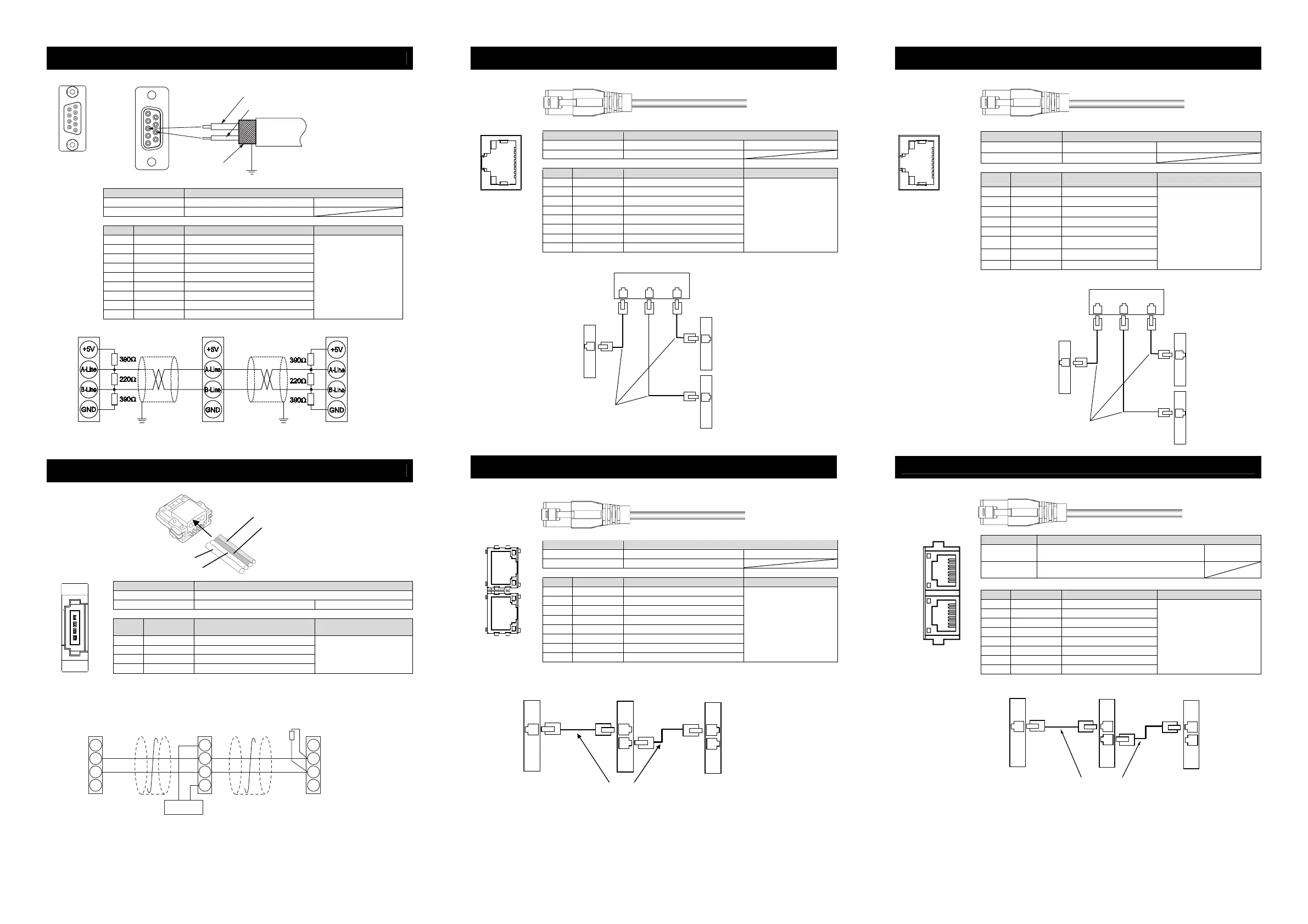
PROFIBUS-DP Type
Refer to the instruction manuals for each fieldbus master unit and mounted PLC for the details.
Connector Name PROFIBUS-DP Connector
Cable Side 9-pin D-sub Connector (Male) Please prepare separately
Controller Side 9-pin D-sub Connector (Female)
Pin No. Signal Name Description Applicable cable diameter
1 NC Disconnected
2 NC Disconnected
3 B-Line Communication Line B (RS485)
4 RTS Request for Sending
5 GND Signal GND (Insulation)
6 +5V +5V Output (Insulation)
7 NC Disconnected
8 A-Line Communication Line A (RS485)
9 NC Disconnected
PROFIBUS-DP Dedicated
Cable
(Type A : EN5017)
Slave Devices
MCON FROFIBUS-DP Type
Master Unit
Grounding resistance at 100
Ω
or less
(Class D grounding)
CompoNet Type
Refer to the instruction manuals for fieldbus master unit and mounted PLC for the details.
Connector Name CompoNet Connector
Cable Side Prepare a connector complied with CompoNet standards.
Controller Side XW7D-PB4-R Produced by OMRON
Pin No.
Signal Name
(Color)
Description Applicable cable diameter
1 BS+ (RD)
Communication Power Supply +
(Note 1)
2 BDH (WT) Signal line H side
3 BDL (BL) Signal line L side
4 BS- (BK)
Communication Power Supply -
(Note 1)
CompoNet Dedicated Cable
Note 1 It is not necessary to supply the communication power. (Internal power source is
used.)
If conducting multi power supply to other slave devices via communication
cables, there is no problem with connecting the power supply to BS+ and BS-
terminals.
BS+
BDL
BDH
BS-
BS+
BDL
BDH
BS-
BS+
BDL
BDH
BS-
Master Unit Slave Devices
Terminal
Resistance
121
Ω
MCON-
CompoNet Type
Connect the terminal
resistor if the unit is
placed at the end of
the network.
24V
Power Supply
Supply power separately to the slave devices
that requires the communication power supply.
It is not necessary to supply communication power
to MCON Unit, however, there is no problem
even if communication power is supplied.
EtherNet/IP Type
Refer to the instruction manuals for fieldbus master unit and mounted PLC for the details.
Connector Name EtherNet/IP Connector
Cable Side 8P8C Modular Plug Please prepare separately
Controller Side 8P8C Modular Jack
Pin No. Signal Name Description Applicable cable diameter
1 TD+ Data sending +
2 TD- Data sending -
3 RD+ Data receiving +
4 – Disconnected
5 – Disconnected
6 RD- Data receiving -
7 – Disconnected
8 – Disconnected
For Ethernet cable, use a
straight STP cable that
possesses the performance of
Category 5 or more.
EtherCAT Type, EtherCAT Motion Type
Refer to the instruction manuals for fieldbus master unit and mounted PLC for the details.
Connector Name EtherCAT Connector, EtherCAT Motion Connector
Cable Side 8P8C Modular Plug Please prepare separately
Controller Side 8P8C Modular Jack
Pin No. Signal Name Description Applicable cable diameter
1 TD+ Data sending +
2 TD- Data sending -
3 RD+ Data receiving +
4 – Disconnected
5 – Disconnected
6 RD- Data receiving -
7 – Disconnected
8 – Disconnected
For Ethernet cable, use a
straight STP cable that
possesses the performance of
Category 5 or more.
PROFINET IO Type
Refer to the instruction manuals for fieldbus master unit and mounted PLC for the details.
Connector Name
PROFINET IO Connector
Cable Side
8P8C Modular Plug Please prepare separately
Controller Side
8P8C Modular Jack
Pin No. Signal Name Description Applicable cable diameter
1 TD+ Data sending +
2 TD- Data sending -
3 RD+ Data receiving +
4 – Disconnected
5 – Disconnected
6 RD- Data receiving -
7 – Disconnected
8 – Disconnected
For Ethernet cable, use a straight
STP cable that possesses the
performance of Category 5 or
more.
CC-Link IE Field Type
Refer to the instruction manuals for each fieldbus master unit and mounted PLC for the details.
Connector Name CC-Link IE Field Connector
Cable Side
Ethernet ANSI/TIA/EIA-568-B Category 5e and above
8P8C modular plug equipped with shield (RJ45)
Please prepare
separately
Controller Side
Ethernet ANSI/TIA/EIA-568-B Category 5e and above
8P8C modular jack equipped with shield (RJ45)
Pin No. Signal Name Description Applicable cable diameter
1 TP0 + Data 0 +
2 TP0 - Data 0 -
3 TP1 + Data 1 +
4 TP2 + Data 2 +
5 TP2 - Data 2 -
6 TP1 - Data 1 -
7 TP3 + Data 3 +
8 TP3 - Data 3 -
It is recommended to prepare a
straight STP cable in Category 5e
or above for the Ethernet cable.
5 1
9 6
Cable
Shield
Red B line (Positive side)
Green A line (Negative side)
1
6
9
5
Front View of
Connector on
Controller side
BK (BS-)
BL (BDL)
RD (BS+)
WT (BDH)
Front View of
Connector on
Controller side
1
2
3
4
Master Unit
Switching Hub
Slave Devices
Ethernet Straight Cable, Category 5 or more
Double shielded cable braided with aluminum foil recommended
MCON- Unit
EtherNet/IP Type
1
8
Front View of
Connector on
Controller side
Front View of
Connector on
Controller side
Master Unit
Switching Hub
Slave Devices
Ethernet Straight Cable, Category 5 or more
Double shielded cable braided with aluminum foil recommended
MCON- Unit
PROFINET IO Type
1
8
Front View of
Connector on
Controller side
OUT
IN
8
1
8
1
Master Unit
Slave Devices
Ethernet Straight Cable Category 5 or more
Double shielded cable braided with aluminum foil recommended
(Note) Terminal resistance is not required
MCON EtherCAT Type or
EtherCAT Motion Type
OUT
IN
IN
OUT
Front View of
Connector on
Controller side
LINK
L.ER
LINK
L.ER
(Note) There is no definition
of IN or OUT on the
communication ports.
Master Unit
Slave Devices
MCON
Ethernet Straight Cable Category 5e or more
There is no distinction of IN and OUT.
Terminal resistance is not required
Double shielded cable braided with aluminum foil recommended
CC-Link IE Field Type

 Loading...


