ibaBM-DPM-S Manual
Issue 2.11
21
8 System integration
8.1 ibaBM-DPM-S in the ibaPDA
environment
In the following examples, only ibaPDA-V6 is referred to as the receiving system. The
topologies apply analogously to ibaLogic. The following also applies to ibaLogic: data
can be received with the ibaBM-DPM-S from the PROFIBUS.
8.1.1 Connection to the DP-Master (unidirectional)
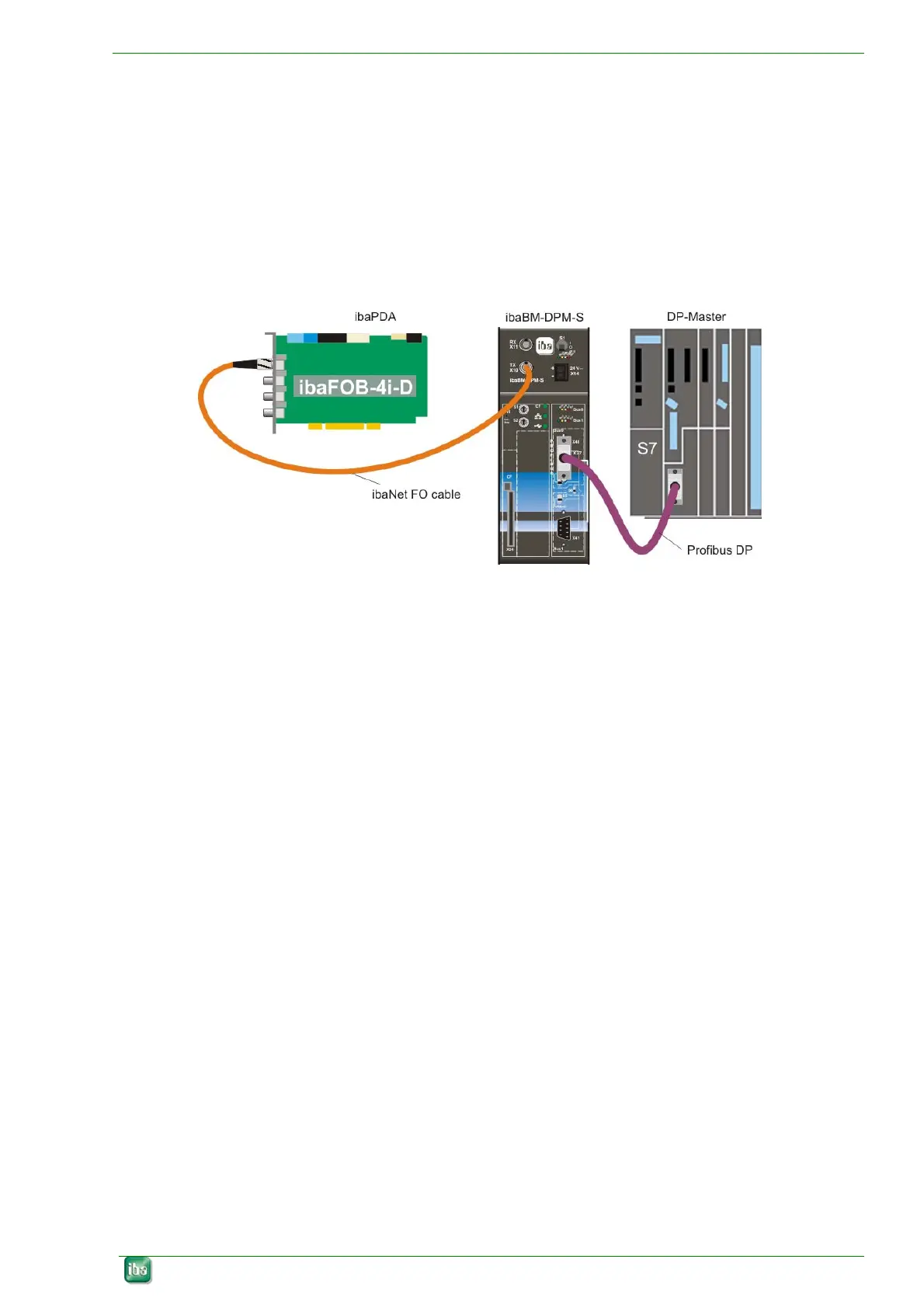
Figure 5: ibaBM-DPM-S connected to the DP master and ibaFOB-4i-D in the measuring PC
The configuration shown above illustrates the ibaBM-DPM-S device connected to a DP
Master device (for example the SIMATIC S7). The measured values can be logged with
a stationary ibaPDA-V6 PC using an ibaFOB-4i–D card.
If the device happens to be the last device on the DP line, as shown in Figure 5, the
corresponding terminating resistor
must be activated. (In the above example, switch S4
is set to ON)
 Loading...