IBC Technologies Inc. 10 VFC 15-150 and VFC 45-225
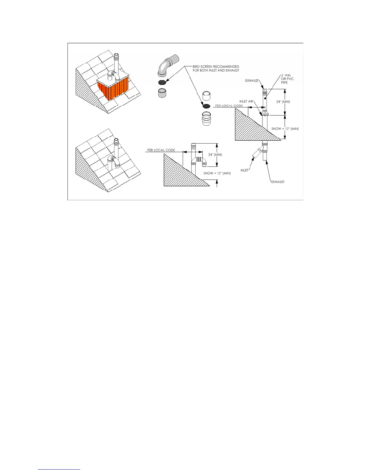
Figure 3 - Rooftop Vent Terminal Configurations
1.4.1.4 Venting Passage Through
Ceiling and Floor
Confirm material meets local codes
pipe clearances - no IBC
requirements; follow local codes
• all piping must be liquid and pressure
tight.
1.4.1.5 Rooftop Vent Termination
Vents must terminate as follows:
• The exhaust pipe can terminate in an
open vertical orientation without
concern about rain infiltration; this
will drain away through a properly
configured condensate trap.
• If used, the intake air pipe is not
typically drained, so it must be
terminated with a down-turned elbow
- see Figure 3). The intake pipe does
not need to penetrate the roof at the
same elevation as the exhaust (as
shown); lower down roof is OK.
• To promote the projection of exhaust
away from the building and from the
intake pipe, reduction of 3” pipe to 2”
is permitted for a maximum lineal
travel of 3’ (e.g. the final 3’)
including 2 x 90° elbows on each side
• Place ¼” mesh bird screen in a
termination fitting. Leave unglued,
and hold in place with a short nipple.
This permits easy access for cleaning
• For roof top venting of multiple boiler
sets, group all intake terminals
together for a common penetration
through a custom cap. Alternatively,
place in the closest proximity
achievable using commonly available
pipe flashing. Similarly group the
exhaust pipes and place the 2 separate
groups of pipes at least 3’ apart (the
closest intake and exhaust pipes shall
be 36” - or more - apart). Use the
same 24” (minimum) vertical
separation as displayed above.
• DO NOT exhaust vent into a
common venting system