IBC Technologies Inc. 31 VFC 15-150 and VFC 45-225
slotted clearance hole on the lower right
corner of the control module; use
needle-nose pliers to move the plastic
jumper tab from the right two terminals
to the left two terminals accessible
through the slotted clearance hole.
Where the IBC controller senses a
signal on the remote connections, it
automatically subordinates its internal
throttle logic, and adopts the external
signal. In such slave mode, temperature
management is also surrendered to the
external controller’s sensors. The
installer only enters Maximum Boiler
Supply and On/Off Differential
temperatures; the boiler will respond to
these as high limit switches.
From the main Installer Setup Menu,
select "Define Load (with desired #)", then
locate and enter "External Control".
Next, configure the load with the
Maximum and Differential temperature
values.
2.7 SET UP & LOAD
DEFINITION
After the boiler is powered up, the
installer can use the keypad and display
to characterize the application, as
follows:
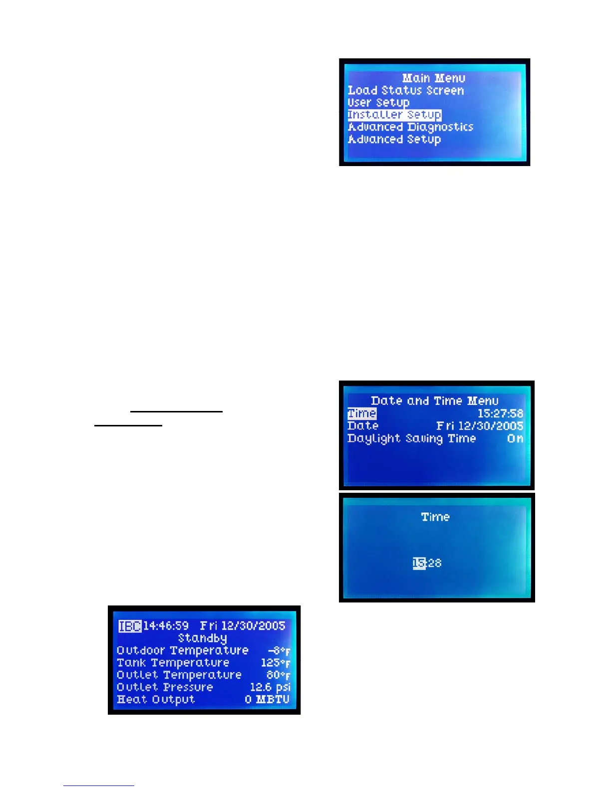
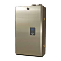
1. In the Standby mode, start by
pressing any key to call up the Main
Menu
2. Using the directional keys, move the
cursor to Installer Setup, then
depress the centre (Enter) key. See
Section 2.4.5. – Passwords if these
are in use or desired.
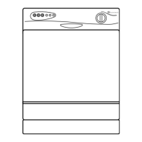
3. Select Date & Time (and Enter),
then move the cursor about to adjust
time (on a 24:00 hour basis), date
and invoke Daylight Savings if
appropriate. Use the upper key to
increase a value (e.g. date, time,
temperature), the bottom key to
reduce. Note that it is often possible
to move in steps of 10 or 100 by
moving the cursor right or left once
a field has been selected for
adjustment. Hit the Enter key to
record the desired / amended
information after each value has
been selected.
4. Use the left-most key to step back to
the Installer Setup screen, and select
Heat Load Configuration for input
of the load characteristics.