IBC Technologies Inc. 16 VFC 15-150 and VFC 45-225
1.5.2 Installation Rules:-
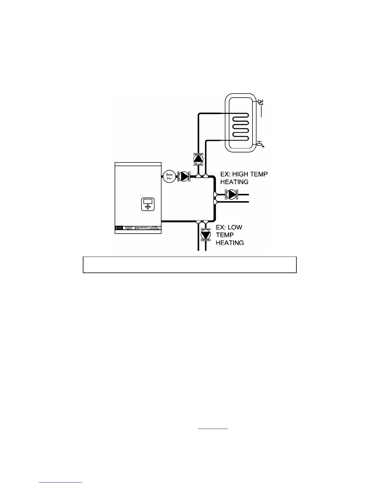
Note: The Boiler Trim element – common to each of the following systems - includes the
pressure relief, fill, expansion tank and air bleed elements. The primary pump can be
located on either the Supply or Return piping sections. See Figure 7.
Features of the preferred Primary /
Secondary piping system:
1. Good circulating water flow
through the boiler irrespective of
load or radiation system head
2. Allows flexible ∆T° control in
secondary loops
3. Adds to the system’s thermal
buffering, to assist in handling
small loads and temperature
transition.
This piping configuration requires an
extra pump. The VFC modulating series
boilers’ controller hosts wiring terminals
and integral relays to simplify
installation and operation of this
preferred layout, offsetting such costs.
For optimal performance, place pumps
on the supply side of secondary loops to
facilitate air evacuation. Use pumps with
internal check valves to avoid ghost
flows and thermal siphoning.
The primary loop temperature may need
to transition from a 180°F domestic
water heating load to a 100°F radiant
floor requirement. The secondary pumps
will swap off/on simultaneously,
provided the pre-set maximum allowable
temperature of the new load is not
exceeded. In the case of the typical
maximum limit for a radiant floor (most
would enter 140°F); the floor pump
Fi
ure 7 - Primar
/ Secondar
Pi
in
stron
l
recommended