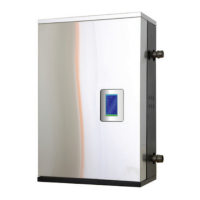
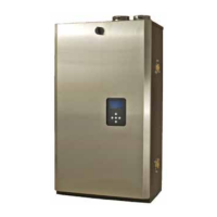
IBC Technologies Inc. 3 VFC 15-150 and VFC 45-225
1 INSTALLATION
1.1 GENERAL
VFC gas-fired modulating boilers are
low pressure, fully condensing units
having variable input ranges (a) 15
MBH (15,000 Btu/hr) to 150 MBH (15-
150 model) and (b) 45 MBH to 225
MBH (45-225 model). The boilers are
approved for either Direct Vent (sealed
combustion) or “Category IV” (indoor
air) applications, providing a great
degree of installation flexibility.
The installer must clearly indicate the
vent category for the installation on
the rating plate using an indelible
marker. See section 1.4 - Venting.
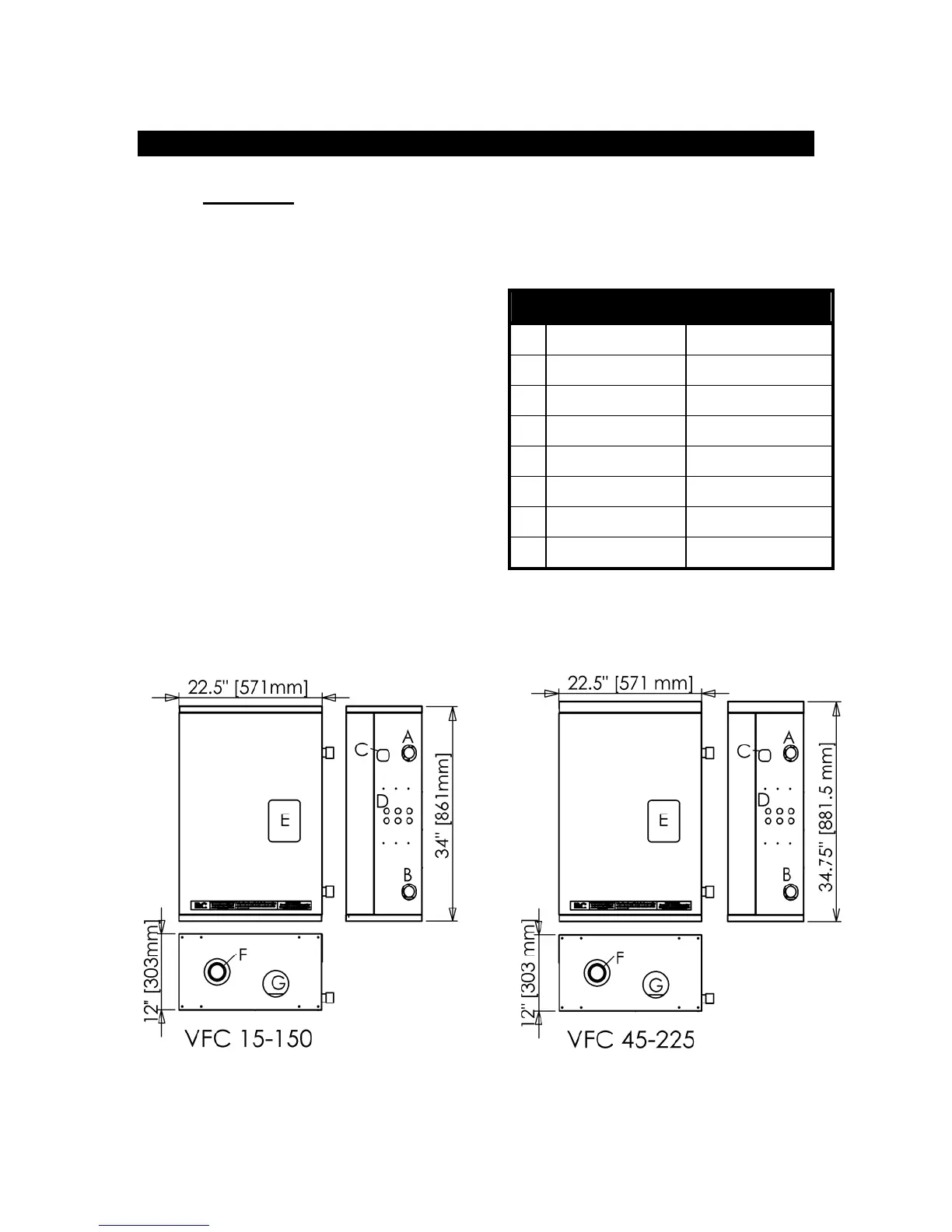
Figure 1 shows outer case dimensions
and piping and electrical holes. Use this
diagram to find a suitable location for
the boiler. (See also Section 1.3 -
Location.)
Table 1 - Connections
Description Size
A water outlet 1¼” NPT-M
B water inlet 1¼” NPT-M
C gas inlet ½” NPT
D knock-outs (6) 1/2”
E LCD display 3/4”
F exhaust vent 4.0" hole
G Combustion air 4.0" hole
Figure 1. - Dimensions/Connections