IBC Technologies Inc. 44 VFC 15-150 and VFC 45-225
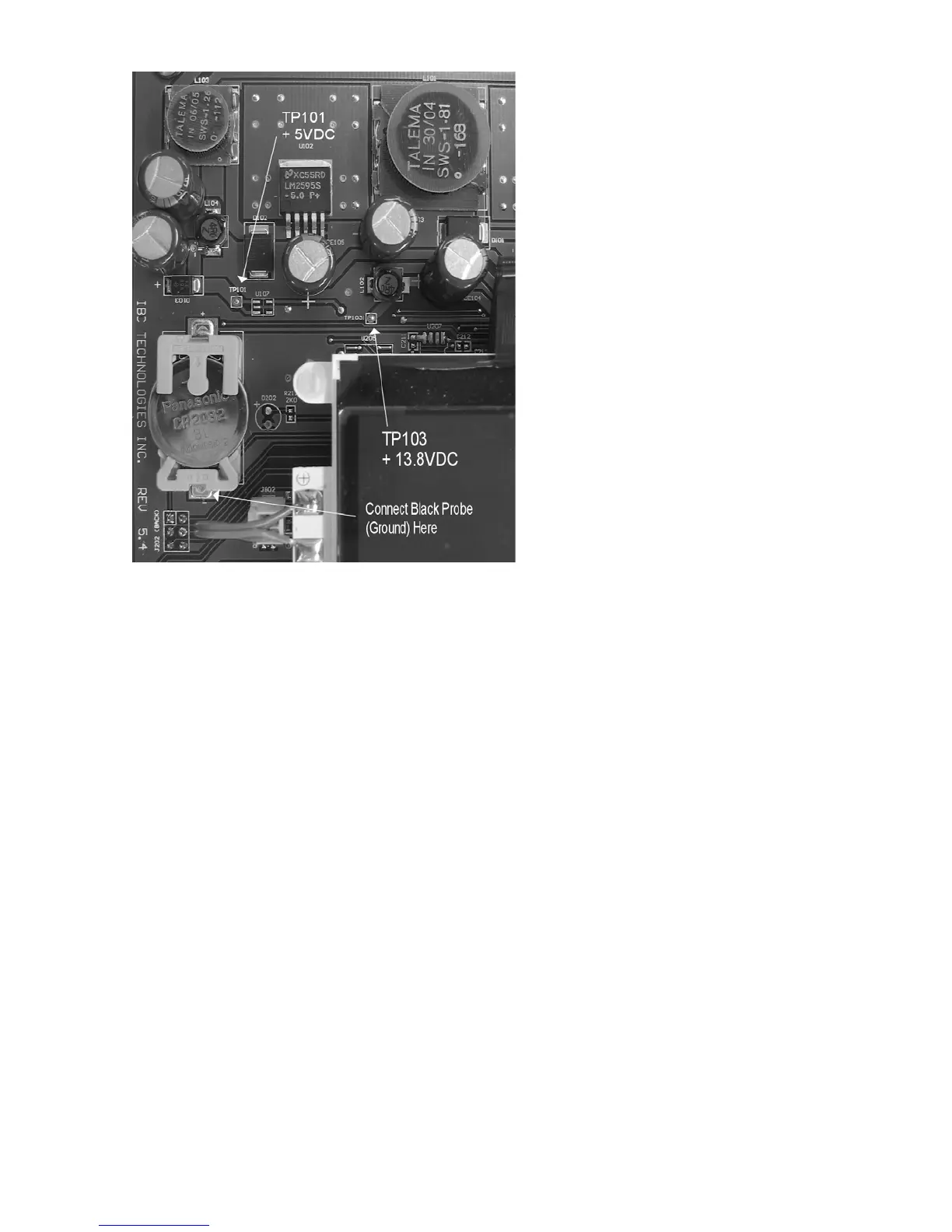
Finally, to measure the sensor output,
connect a DC volt meter between points
“J501-33” (located on the footprint of
the 34 pin connector – immediately
below the right leg of the LCD display -
second pin from bottom right) and GND
(see above). With the fan off, the
measure should read 0.5V
DC. With a Fan
Pressure of approx. 300, the meter will
read 1.5v (approx.). Note:- this
component is a sensor, not a switch; do
not over-pressurize by blowing into the
air reference lines. Maximum pressure
capacity is 40” w.c. @ 20 C but only
10” w.c. @ 5C.
4.3.2.4 Water Pressure Sensors
Go to the Advanced Diagnostics screen,
and check the top 2 display lines —
Inlet Pressure and Outlet Pressure. With
the pumps at rest and system pressure
of 12.5 psi, the Inlet Pressure and
Outlet Pressure sensor values should
read 235 +/- 5. Of the two, while at rest,
the Inlet normally reads 1 – 2 points higher, reflecting the extra 2’ of water column. The third
displayed line Delta Pressure will normally indicate a value of approx. 20 with pump in
operation. The location of the boiler pump will determine the movement of valid sensor
values; in general, inlet pressure will increase while the outlet will decrease when the pump
starts.
Check operation of both sensors by isolating the boiler from its system piping, closing the
system fill valve then cracking the pressure relief valve; both signals should reflect declining
pressure. If one or both remain “fixed”, drain boiler and replace sensor(s), or dislodge any
blocking debris from sensor inlet channel and reinsert. To remove a red-coloured “502”
sensor, it is necessary to release a stainless steel retaining clip at the base of the unit – see part
#65 on page 55. Before refilling system, ensure the 502 sensor retainer clips are properly re-
installed. The black “505” sensors are threaded and do not use the retainer clip system.
4.3.2.5 Hi-Limit Switch (water and vent)
Check resistance between leads. If resistance is very low, temperature should be acceptable.
If resistance is very high, temperature should be out of bounds. A simple means of checking
whether a high limit switch is open is by measuring the AC voltage across the device. If the
reading is 24 VAC the switch is open. If a 0VAC reading is shown, it is closed. NEVER
connect an ohm-meter or continuity checker across a live circuit.