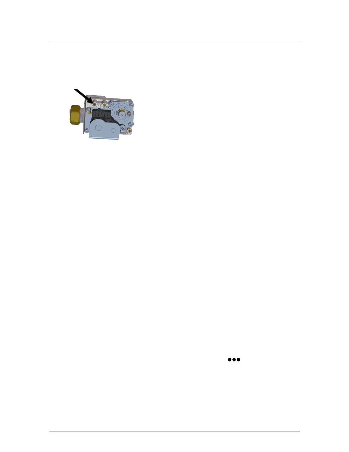
1. Shut off the gas supply. You will be measuring the inlet gas supply from the test port (see
). Do not perform a test from the manifold gas pressure test port.
2.
On the gas valve, loosen the inlet gas pressure test port screw counter-clockwise.
Location of inlet gas pressure test port
3. Attach the manometer to the inlet gas pressure test port.
4. To measure the inlet gas pressure, switch on the gas supply.
5.
When the boiler is operating at high fire, measure the gas pressure. Ensure that you have
a load configured (reset heating, set point, or DHW). This load should be large enough to
allow the boiler to operate at high fire for over 10 minutes.
The gas pressure for natural gas should be around 7" wc at high fire and 11" wc for
propane.
6. After completing the inlet gas pressure test, switch off the gas supply.
7. Remove the manometer from the inlet gas pressure test port.
8. Tighten inlet gas pressure test port screw.
9. Switch on the gas supply, and return the boiler to normal operation.
6.3.3.2 Performing a combustion test and adjustment
The High Fire (gas-air ratio) adjustment screw will have to be adjusted to attain optimum
combustion results whenever fuel conversion is undertaken, however, no mixture adjustment
must be performed unless done by a qualified technician using properly functioning and
calibrated combustion analyzing equipment.
1. Turn on the boiler’s external gas shut-off valve.
2. Give the boiler a call for heat.
3. To run the boiler at high fire, you can set the heat-out value in Test Operation mode to the
maximum MBH for the boiler. To do this, on the controller, go to > Test Operation >
In the Fan Test: Heat Out field, tap 0 MBtu, then enter the maximum MBH.
When the boiler reaches high fire, insert the combustion analyzer test probe into the flue
gas test port. Then verify that the CO2 reading is within the combustion test targets at
Table 10 values.
Section: Boiler operation