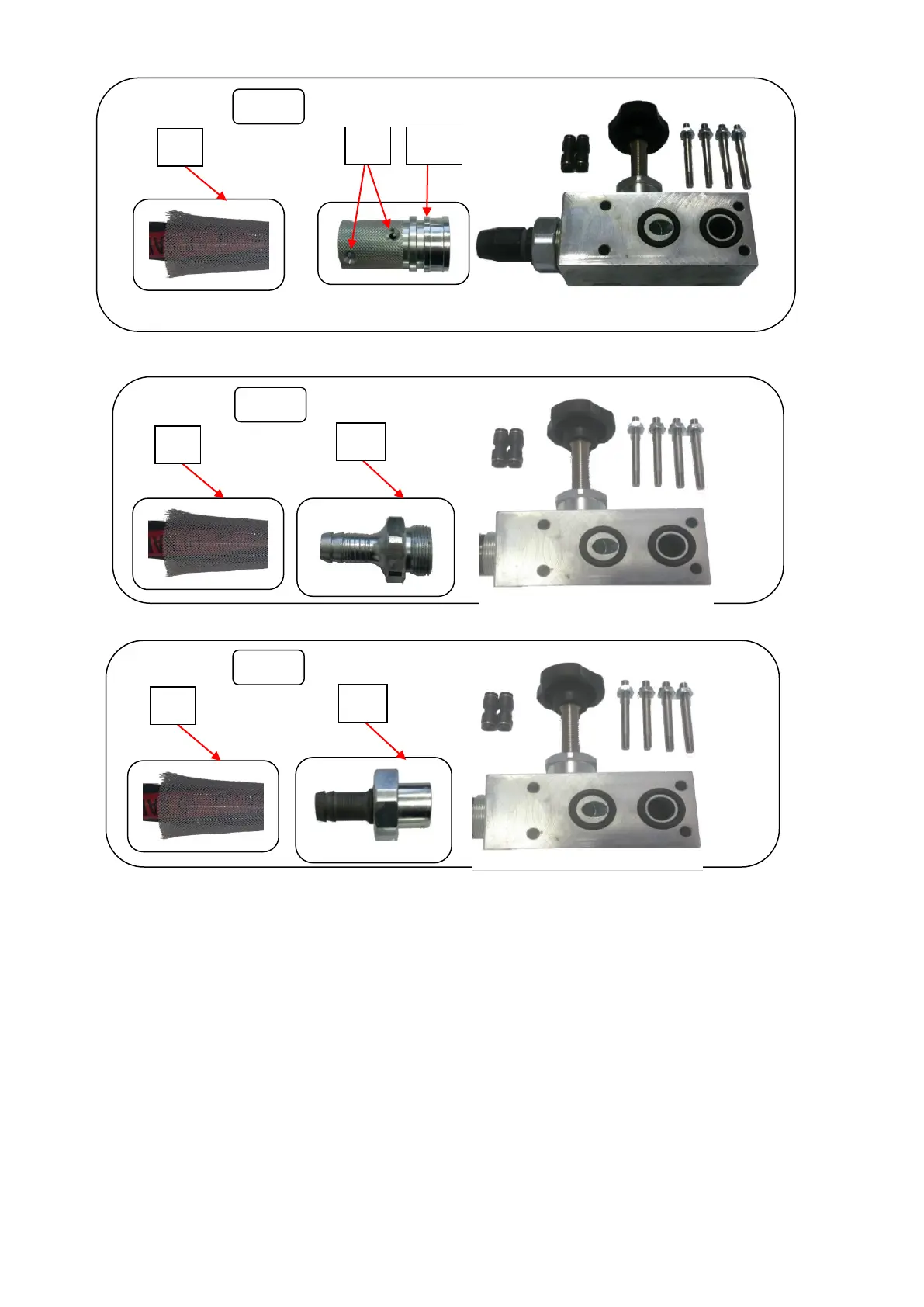
The figures above (1-2-3) show the three abrasive valve fixing and connecting options.
With reference to options shown in figure 2 (steel fitting) and in figure 3 (tungsten fitting), release
the hose jubilee clip (8) and pull out the hose.
With reference to option shown in figure 1 (quick connect fitting) unscrew the screws (9) pull them
out completely from the detail (9A).
Turn the abrasive hose (8) anticlockwise to extract it.
To install the new abrasive hose, repeat the disassembly operations conversely until the new hose
has been installed.