FC compatibility
2, 4, 8 Gigabit
Cables
Cables are the responsibility of the customer.
Use multimode fiber optic cables with shortwave lasers that adhere to the following
specifications:
v OM3: Multimode 50/125 micron fiber, 2000 MHz x km bandwidth
v OM2: Multimode 50/125 micron fiber, 500 MHz x km bandwidth
v OM1: Multimode 62.5/125 micron fiber, 200 MHz x km bandwidth
Because core sizes are different, OM1 cables can only be connected to other OM1 cables. For best
results, OM2 cables should not be connected to OM3 cables. However, if an OM2 cable is
connected to an OM3 cable, the characteristics of the OM2 cable apply to the entire length of the
cables. The following table shows the supported distances for the different fiber optic cable types
at different link speeds.
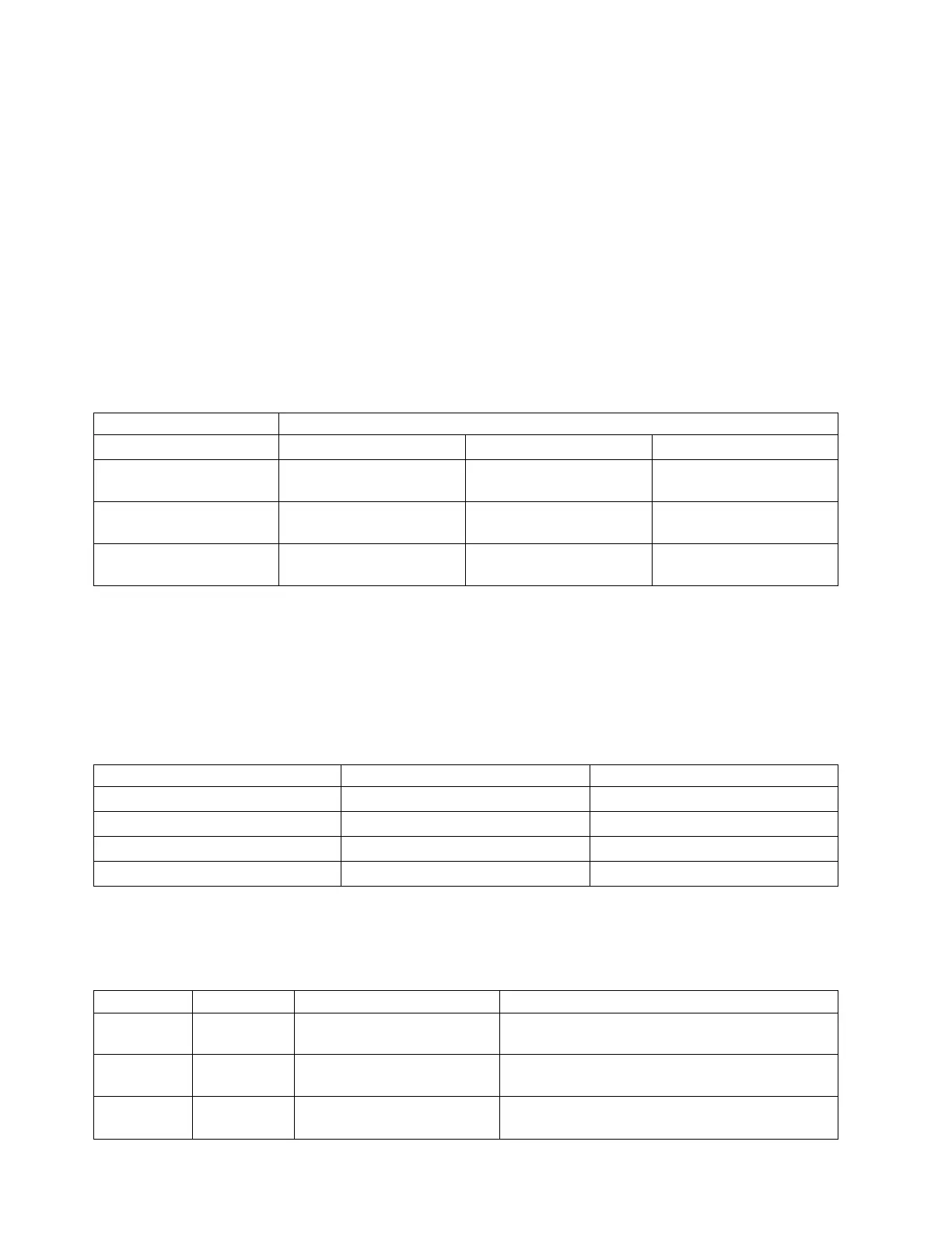
Table 30. Supported distances for multimode fiber optic cables
Header Cable Type and Distance
Rate OM1 OM2 OM3
2.125 Gbps 0.5 meters to 150 meters
(1.64 feet to 492.12 feet)
0.5 meters to 300 meters
(1.64 feet to 984.25 feet)
0.5 meters to 500 meters
(1.64 feet to 1640.41 feet)
4.25 Gbps 0.5 meters to 70 meters
(1.64 feet to 229.65 feet)
0.5 meters to 150 meters
(1.64 feet to 492.12 feet)
0.5 meters to 380 meters
(1.64 feet to 1246.71 feet)
8.5 Gbps 0.5 meters to 21 meters
(1.64 feet to 68.89 feet)
0.5 meters to 50 meters
(1.64 feet to 164.04 feet)
0.5 meters to 150 meters
(1.64 feet to 492.12 feet)
Adapter LED
Green and yellow LEDs can be seen through openings in the mounting bracket of the adapter. Green
indicates firmware operation and yellow signifies port activity. Table 31 summarizes the link rate
conditions. There is a 1-second pause when the LED is off between each group of fast flashes (2, 3, or 4).
Observe the LED sequence for several seconds to be sure that you have correctly identified the state.
Table 31. Normal LED states
Green LED Yellow LED State
Slow flash Off Normal, link inactive or not started
On 2 fast flashes 2 Gbps link rate - normal, link active
On 3 fast flashes 4 Gbps link rate - normal, link active
On 4 fast flashes 8 Gbps link rate - normal, link active
Power-on self test (POST) conditions and results are summarized in Table 32. These states can be used to
identify abnormal states or problems. Follow the action to be taken for each condition.
Table 32. POST conditions and results
Green LED Yellow LED State Action to be taken
Off Off Wake-up failure (dead board) Perform AIX, IBM i, or Linux operating system
diagnostics procedure.
Off On POST failure (dead board) Perform AIX, IBM i, or Linux operating system
diagnostics procedure.
Off Slow flash Wake-up failure monitor Perform AIX, IBM i, or Linux operating system
diagnostics procedure.
106 Managing PCIe adapters
 Loading...