Because core sizes are different, OM1 cables can only be connected to other OM1 cables. For best
results, OM2 cables should not be connected to OM3 cables. However, if an OM2 cable is
connected to an OM3 cable, the characteristics of the OM2 cable apply to the entire length of the
cables.
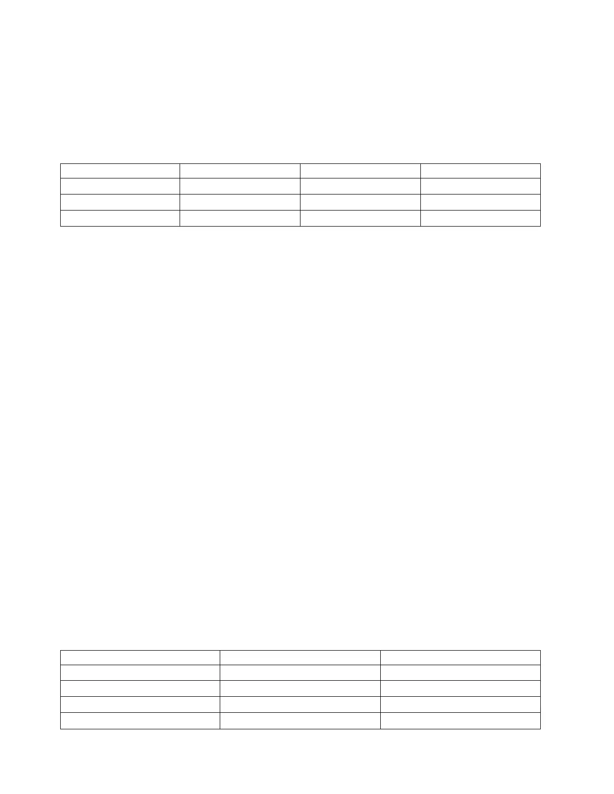
The following table shows the supported distances for the three different cable types at the three
different link speeds.
Table 12. Supported cable distances by link speed
Cable type 2.125 Gbps 4.25 Gbps 8.5 Gbps
OM3 0.5 m - 500 m 0.5 m - 380 m 0.5 m - 150 m
OM2 0.5 m - 300 m 0.5 m -150 m 0.5 m - 50 m
OM1 0.5 m - 150 m 0.5 m - 70 m 0.5 m - 21 m
Maximum number
For the maximum adapters supported, see the PCI adapter placement topic collection for your
system.
Operating system or partition requirements
If you are installing a new feature, ensure that you have the software that is required to support the new
feature and that you determine whether there are any prerequisites for this feature and attaching devices.
To check for the prerequisites, see IBM Prerequisite website (www-912.ibm.com/e_dir/eServerPrereq.nsf).
The adapter is supported on the following versions of the operating systems:
v AIX
– AIX Version 7.1, or later
– AIX Version 6.1, or later
– AIX Version 5.3, or later
v Linux
– Red Hat Enterprise Linux 6.1 for POWER, or later
– SUSE Linux Enterprise Server 11, Service Pack 1, or later (with update package)
– For support details, see the Linux Alert website (www14.software.ibm.com/webapp/set2/sas/f/
lopdiags/info/LinuxAlerts.htm)
v IBM i
– IBM i 7.1, or later.
– IBM i 6.1, or later.
Adapter LED
Green and yellow LEDs can be seen through openings in the adapter mounting bracket. Green indicates
firmware operation and yellow signifies port activity. Table 13 summarizes the link rate conditions. There
is a 1-second pause when the LED is off between each group of fast flashes (2, 3, or 4). Observe the LED
sequence for several seconds to be sure that you have correctly identified the state.
Table 13. Normal LED states
Green LED Yellow LED State
Slow flash Off Normal, link inactive or not started
On 2 fast flashes 2 Gbps link rate - normal, link active
On 3 fast flashes 4 Gbps link rate - normal, link active
On 4 fast flashes 8 Gbps link rate - normal, link active
28 Power Systems: Managing PCI adapters for the IBM Power 710 Express or the IBM Power 730 Express