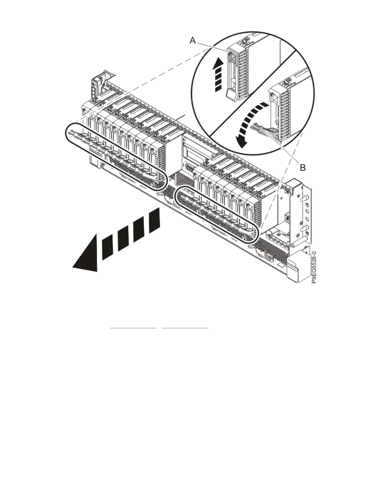
Figure 70. Partially removing the front drives and llers
a) Push the drive tab (A) to release the drive lever (B).
b) Using the drive lever, pull the drive and ller about 2.5 cm (1 in) from the system.
c) Repeat steps “3.a” on page 79 - “3.b” on page 79 for the other drives and llers.
4. Label and disconnect the signal cable (A) and the power cable (B) from the disk drive backplane as
shown in the following gure.
Unlatch the clips that secure the connectors to the disk drive backplane.
Drive backplanes for the 9009-41A, 9009-41G, 9009-42A, 9009-42G, or 9223-42H
79
 Loading...