6.2.1.9 Disable SCSI Parity Check (Position 11)
Grounding this pin will disable SCSI Parity checking.
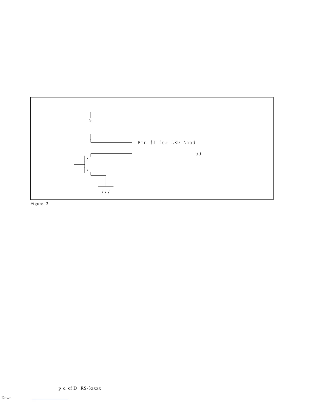
6.2.1.10 LED pins (Position 12)
The LED pins are used to drive an external Light Emitting Diode. Up to 30 mA of sink current capability
is provided. The LED Anode must be tied to the current limited + 5 V source provided on Pin #1 of the
Option Jumper Block. The LED Cathode is then connected to the Pin #2 to complete the circuit.
+5V
o
³
>
< 620 Ohm
>
³
ÀÄÄÄÄÄÄÄÄÄÄÄÄÄ
o Pin #1 for LED Anode
ÚÄÄÄÄÄÄÄÄÄÄÄÄÄ
o Pin #2 for LED Cathod
³
/
ÄÄÄ´
³
\
ÀÄÄÄÄ¿
³
ÄÄÁÄÄ
///
Figure 25. LED Circuit
34 OEM Spec. of DDRS-3xxxx

 Loading...