location in relation to the cable entry point are critical to the successful installation
of a top cable exit.
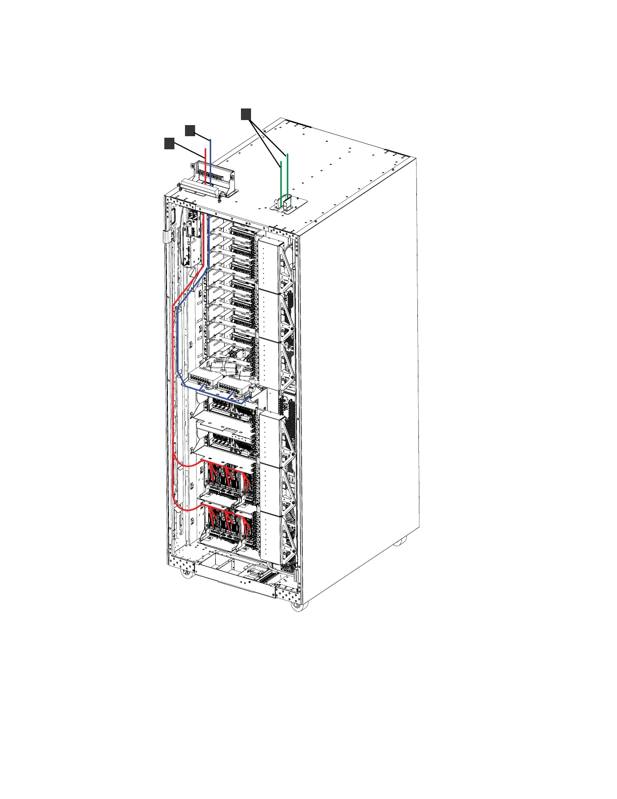
Figure 18 illustrates the location of the cabling for the top exit bracket for Fibre
cable feature. When you order a top exit feature, the feature includes clamping
hardware, internal cable routing brackets for rack 1 or rack 2, and two top exit
mainline power cords for each rack. The following notes provide more information
about the color-coded cable routing and components in Figure 18.
1 Customer Fibre Channel host cables. The Fibre Channel host cables, shown
in red, are routed from the top of the rack down to I/O enclosure host adapter
cards.
1
2
f2c01680
3
Figure 18. DS8000 with top exit feature installed (cable routing and top exit locations)
144 Introduction and Planning Guide