18 IBM Flex System FC5022 16Gb SAN Scalable Switch User’s Guide
Installing and removing an SFP+ transceiver
2
A preferred order of cabling exists. Two of the 12-port licenses (port 0 and port 29) are factory
assigned. Use these ports first. Refer to Figure 9.
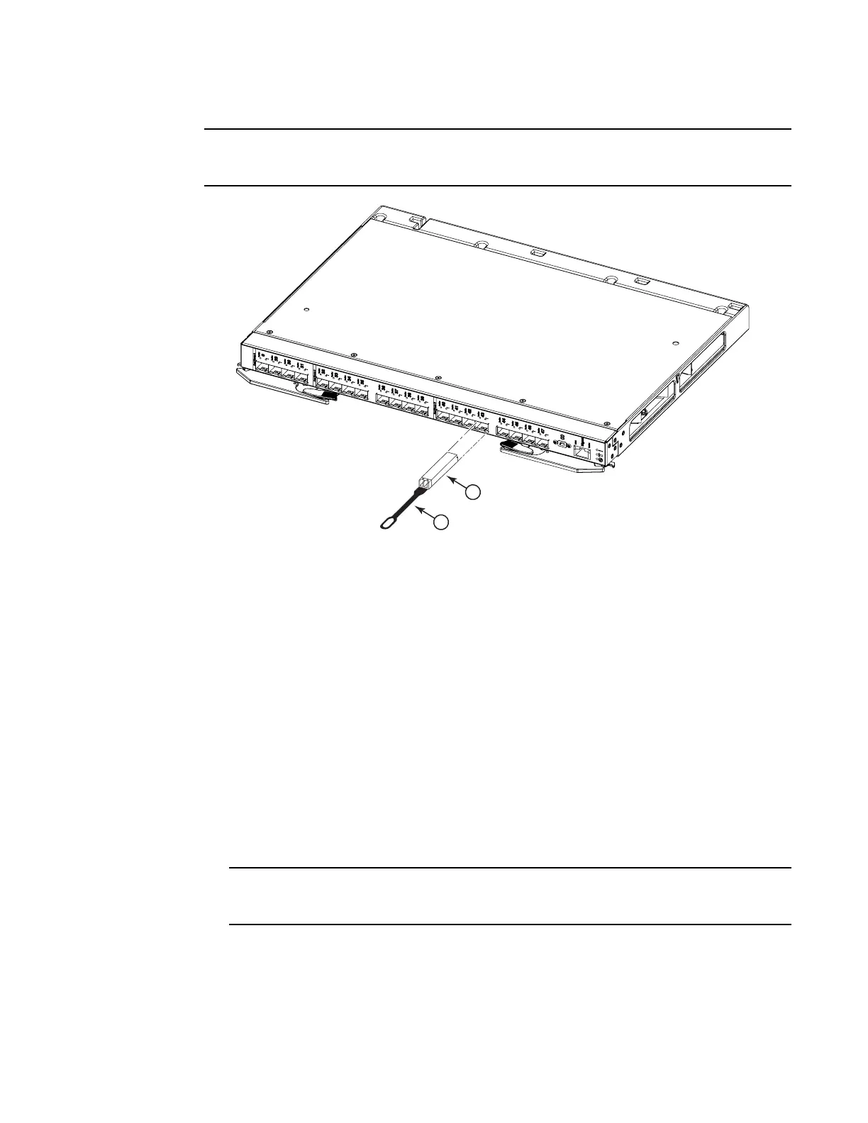
FIGURE 5 SFP+ transceiver installation
6. Connect the fiber-optic cable to the SFP+ transceiver. For information about protecting the
cable, refer to “Handling an SFP+ transceiver” on page 16.
7. Check the LEDs on the switch. When the switch is operating correctly, the green link LED is lit.
For information about the status of the switch LEDs, see “Information LEDs” on page 23.
Removing an SFP+ transceiver
To remove an SFP+ transceiver, complete the following steps:
1. Read the safety information that begins on page vii and “System reliability guidelines” on
page 11.
2. Read the information in “Handling an SFP+ transceiver” on page 16.
3. Remove the fiber-optic cable from the SFP+ module that you want to replace.
To avoid damage to the cable or the SFP+ transceiver, make sure you disconnect the
fiber-optic cable before you remove the SFP+ module.
4. Unlock the SFP+ transceiver by gently pulling the tab straight out.
5. Place the SFP+ transceiver in a static-protective package.
6. Insert another SFP+ transceiver into the port (see “Inserting an SFP+ transceiver” on page 17),
or insert a dust cap, as shown in Figure 6.
1 Pull tab 2 SFP+ transceiver