EasyManuals Logo

IBM Flex System V7000 Installation Guide

IBM Flex System V7000
56 pages
To Next Page IconTo Next Page
To Previous Page IconTo Previous Page
Page #21 background imageLoading...
Page #21 background image
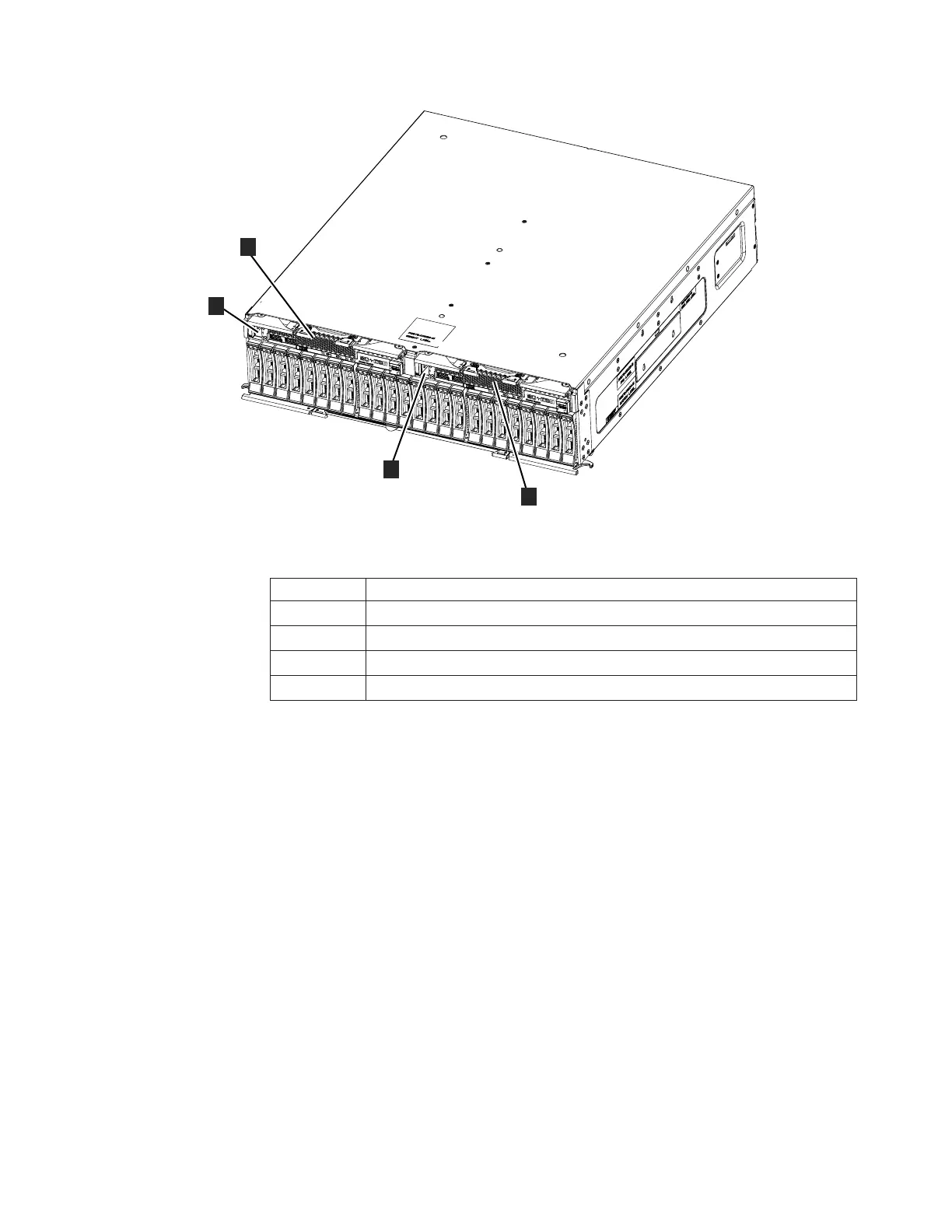
Table 2. Control enclosure components
Component Description
1 SAS port 1, node canister 1 (left)
2 Node canister 1 (left)
3 Node canister 2 (right)
4 SAS port 1, node canister 2 (right)
Expansion enclosure components
Figure 2 shows the front view of an expansion enclosure and two expansion
canisters. It is shown with 24 SFF 2.5-inch drives installed. Your enclosure might
contain a different number of drives.
Both expansion canisters have 2 mini-SAS ports. The left-to-right features are SAS
Port 1 and SAS Port 2.
Note: Expansion canisters are sometimes referred to as an Expansion module as
printed on the bezel.
ite00028
1
2
3
4
Figure 1. Control enclosure and node canisters
Figure 2. Expansion enclosure and canisters
Chapter 1. Before you begin the installation 5

Table of Contents

Other manuals for IBM Flex System V7000

Questions and Answers:

Question and Answer IconNeed help?

Do you have a question about the IBM Flex System V7000 and is the answer not in the manual?

IBM Flex System V7000 Specifications

General IconGeneral
Form Factor2U
ModelIBM Flex System V7000
CategoryStorage
Power SupplyDual redundant power supplies
Storage ControllerDual active-active controllers
RAID LevelsRAID 0, 1, 5, 6, 10
Maximum Drives240
Expansion EnclosuresUp to 9
Drive Types SupportedSSD, HDD
Host Interface Ports8 Gbps FC
ScalabilityScalable with expansion enclosures
Operating Temperature5°C to 40°C
Management InterfaceWeb-based GUI, CLI, SMI-S

Related product manuals