ite00027
1
2
3
4
5
6
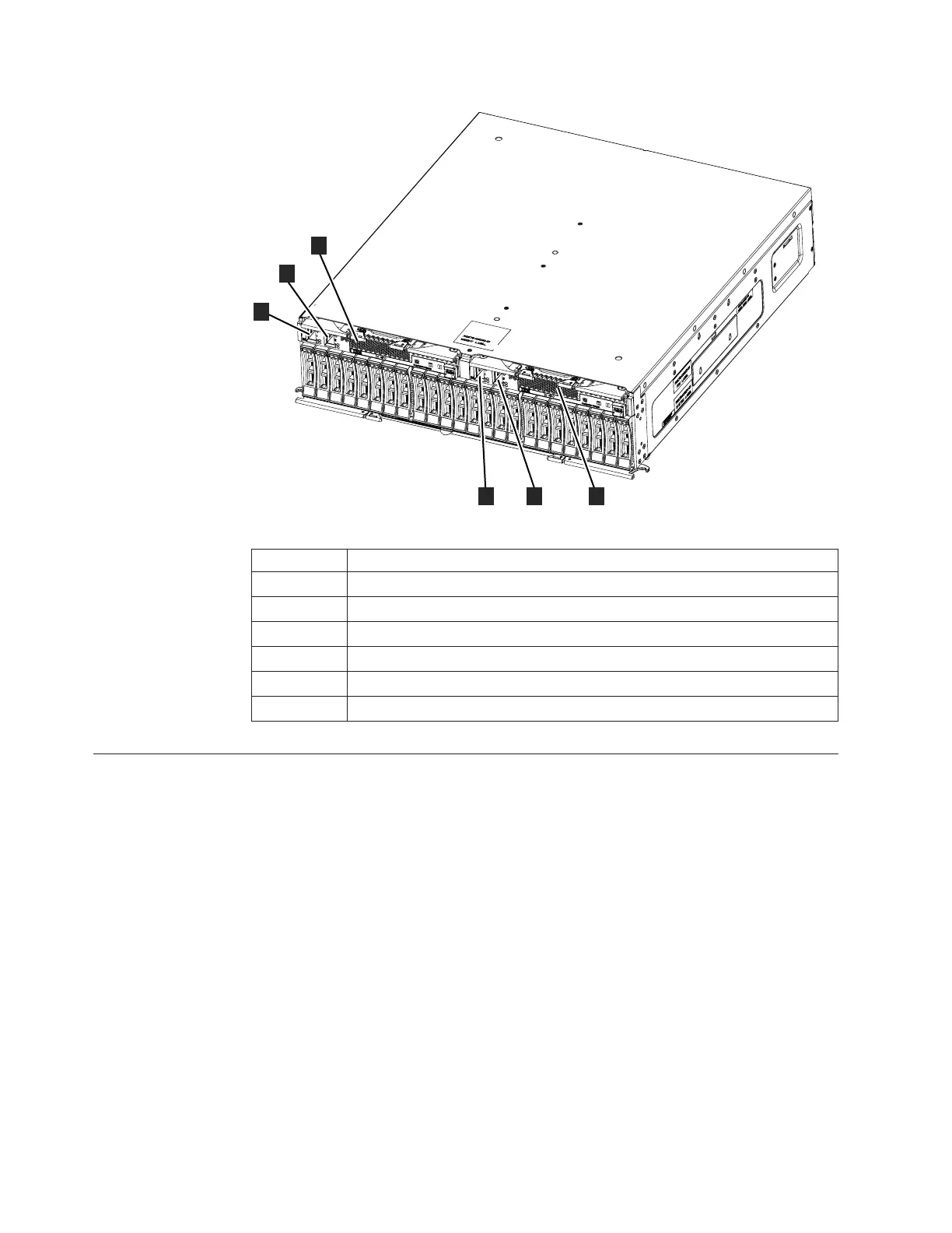
Table 3. Expansion enclosure components
Component Description
1 SAS port 1, expansion canister 1 (left)
2 SAS port 2, expansion canister 1 (left)
3 Expansion canister 1 (left)
4 Expansion canister 2 (right)
5 SAS port 2, expansion canister 2 (right)
6 SAS port 1, expansion canister 2 (right)
Step 3. Verifying environmental requirements
Certain requirements for the physical site must be met to ensure that your system
works reliably. This step includes verifying that adequate space in a suitable
chassis is available and that requirements for power and environmental conditions
are met. This documentation assumes that you have completed the physical
planning for the environment of your system.
If you have not done the environmental planning for your system, see the Flex
System V7000 Storage Node physical installation planning topic in the Flex System
V7000 Storage Node Information Center.
If your system contains more than one control enclosure, you must configure the
Fibre Channel switch for correct zoning between the control enclosures. See the
configuring topics in the Flex System V7000 Storage Node Information Center that
contain information about zoning rules and zoning details.
You must use a supported web browser. Verify that you are using a supported web
browser from the following website:
6 Flex System V7000 Storage Node: Installation Guide

 Loading...


