4. Use the information in Table 8 to verify the state of the light emitting diodes
(LEDs) on the expansion enclosure. Verify that no faults are detected. See the
IBM Flex System V7000 Storage Node Troubleshooting, Recovery, and Maintenance
Guide PDF on the CD if problems are encountered.
Attention: Do not continue if any faults are indicated by the LEDs.
Results
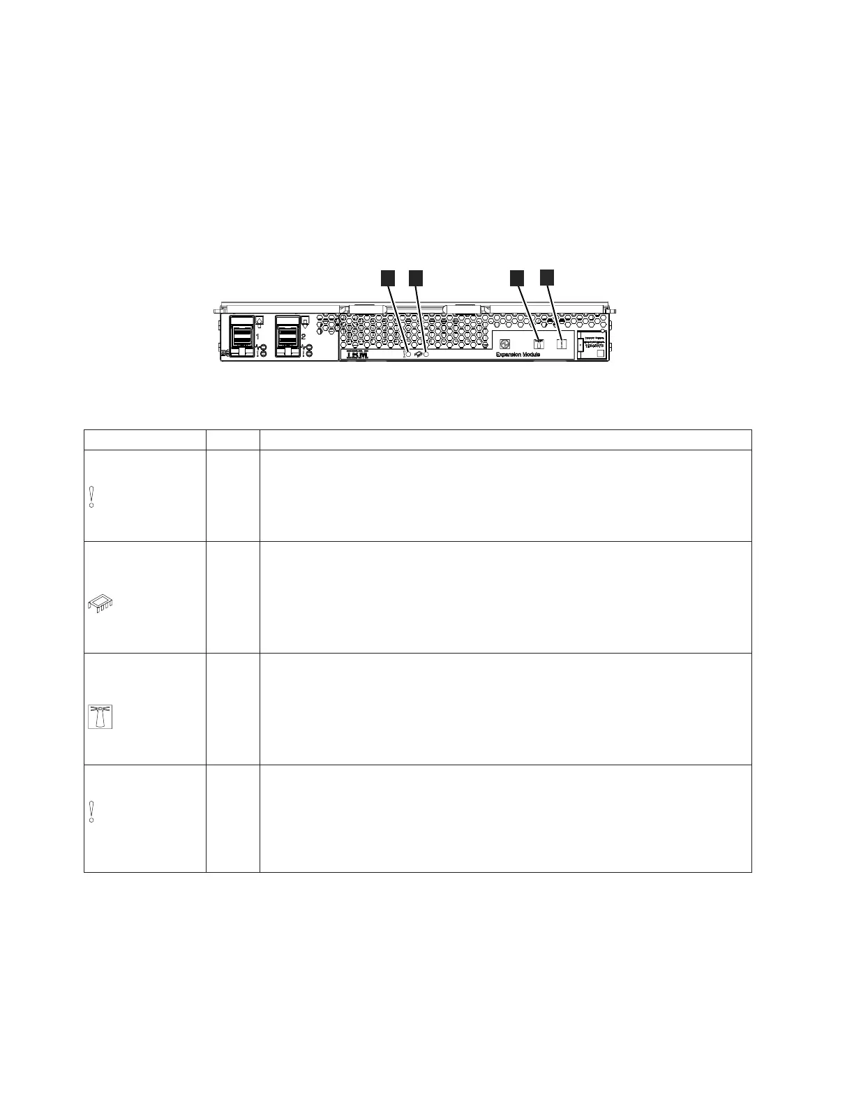
Figure 15 shows the location of the LEDs on the front of the expansion enclosure.
Table 8. Expansion enclosure LED descriptions
LED Name Color States
1 Expansion
canister fault
amber
v OFF – There are no isolated FRU failures on the expansion canister.
v ON SOLID – There are one or more isolated failures in the expansion canister
requiring service or replacement. See the IBM Flex System V7000 Storage Node
Troubleshooting, Recovery, and Maintenance Guide PDF on the CD for troubleshooting
procedures.
2 Expansion
canister Internal
fault
amber
v OFF – There are no failures isolated to internal components of the expansion
canister.
v ON SOLID – An internal component requires service or replacement. See the IBM
Flex System V7000 Storage Node Troubleshooting, Recovery, and Maintenance Guide
PDF on the CD for troubleshooting procedures.
v BLINKING – An internal component is being identified on this expansion canister.
3 Expansion
canister or
enclosure identify
blue
v OFF – The expansion canister is not in identify state by the controller management
system.
v ON SOLID – The expansion canister has been identified in response to the
controller management system.
v BLINKING – This occurs during power on and power-on self-test (POST)
activities.
4 Expansion
enclosure fault
amber .
v OFF – There are no isolated failures on the expansion enclosure.
v ON SOLID – There are one or more isolated failures in the expansion enclosure
requiring service or replacement. See the IBM Flex System V7000 Storage Node
Troubleshooting, Recovery, and Maintenance Guide PDF on the CD for troubleshooting
procedures.
ite00057
1
2
3
4
Figure 15. LEDs on the expansion enclosure
24 Flex System V7000 Storage Node: Installation Guide

 Loading...


