EasyManuals Logo

IBM Flex System V7000 Installation Guide

IBM Flex System V7000
56 pages
To Next Page IconTo Next Page
To Previous Page IconTo Previous Page
Page #34 background imageLoading...
Page #34 background image
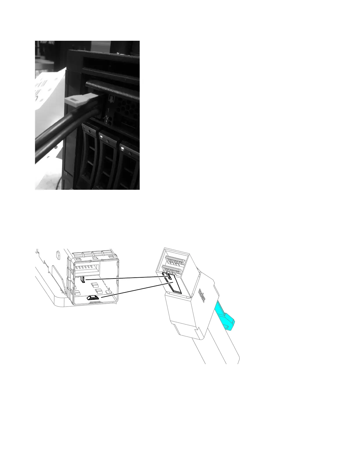
Figure 12 shows the SAS cable socket and connector keys.
Note: If you make a mistake during cabling and must unplug a SAS cable, pull
the blue tab to release the cable.
Procedure
1. Review the following illustration before attaching the SAS cables. Figure 13 on
page 19 illustrates the SAS cabling for a maximum configuration with a 4939
control enclosure and two type 4939 expansion enclosures installed in a Flex
System chassis along with seven additional type 2076 expansion enclosures
installed in a rack external to the Flex System chassis. Your system might
ite00055
Figure 11. Correct SAS cable connection
ite00043
Figure 12. HD SAS cable socket and connector
18 Flex System V7000 Storage Node: Installation Guide

Table of Contents

Other manuals for IBM Flex System V7000

Questions and Answers:

Question and Answer IconNeed help?

Do you have a question about the IBM Flex System V7000 and is the answer not in the manual?

IBM Flex System V7000 Specifications

General IconGeneral
Form Factor2U
ModelIBM Flex System V7000
CategoryStorage
Power SupplyDual redundant power supplies
Storage ControllerDual active-active controllers
RAID LevelsRAID 0, 1, 5, 6, 10
Maximum Drives240
Expansion EnclosuresUp to 9
Drive Types SupportedSSD, HDD
Host Interface Ports8 Gbps FC
ScalabilityScalable with expansion enclosures
Operating Temperature5°C to 40°C
Management InterfaceWeb-based GUI, CLI, SMI-S

Related product manuals