Table 6 defines the various LED states for the node canisters in the IBM Flex
System V7000 Storage Node.
Table 6. LED state descriptions used in the IBM Flex System V7000 Storage Node
State Description
Off The LED is continuously not lit or off.
Blinking slowly The LED turns on and off at a frequency of 1 Hz: It is on for 500 ms,
then off for 500 ms, then repeats.
Blinking The LED turns on and off at a frequency of 2 Hz: It is on for 250 ms,
then off for 250 ms, then repeats.
Blinking fast The LED turns on and off at a frequency of 4 Hz: It is on for 125 ms,
then off for 125 ms, then repeats.
On The LED is continuously lit or on.
Flashing The LED is lit to indicate some activity, then turns off. The rate and
duration that the LED is lit depends on the rate and duration of the
activity.
Procedure
1. When the power on LEDs reach the blinking state, the control enclosure is
powered on automatically. The green power on LEDs are on solid when the
enclosure is powered on successfully. See Table 5 on page 21.
Note: If the control enclosure does not automatically power on, use the CMM
or Flex System Manager to manually power on the node.
2. Verify that no faults are detected on the control enclosure after powering on.
Use Table 7 to verify the state of the LEDs on the control enclosure. See the
IBM Flex System V7000 Storage Node Troubleshooting, Recovery, and Maintenance
Guide PDF on the CD if problems are encountered.
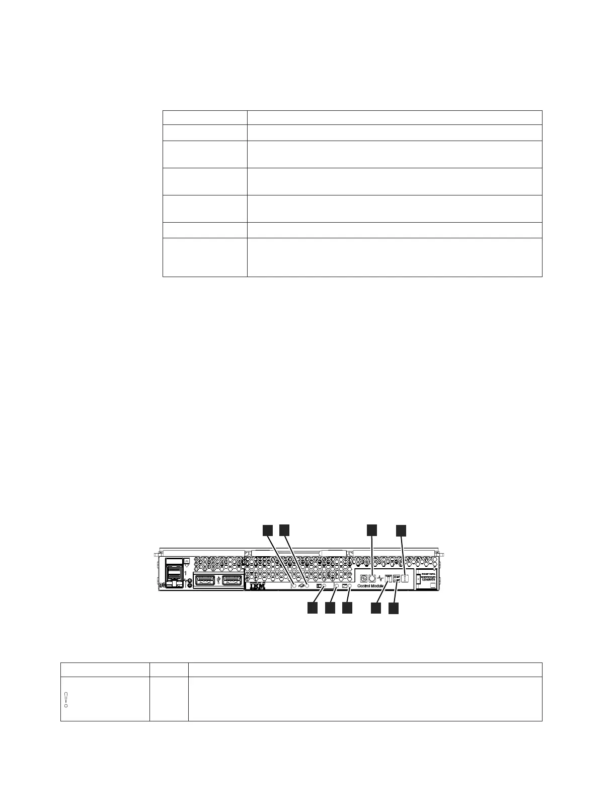
Figure 14 shows the location of the LEDs on the front of the control enclosure.
If you have not installed an expansion enclosure, you have completed all the
necessary steps. Otherwise, continue at Step 3 on page 23.
Attention: Do not go to step 3 on page 23 if any faults are indicated by the
LEDs.
Table 7. Node Canister LED descriptions
LED Name Color States
1 Canister fault
amber
v OFF – There are no isolated failures in the canister.
v ON SOLID – See the IBM Flex System V7000 Storage Node Troubleshooting, Recovery,
and Maintenance Guide PDF on the CD for troubleshooting information.
ite00056
1
2
3
5
6
4
7
8
9
Figure 14. LEDs on the control enclosure (node canister)
22 Flex System V7000 Storage Node: Installation Guide

 Loading...


