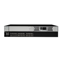
Figure 9 shows the location of the LEDs on the port side of the switch. See “LED
patterns and recommended actions” for details about how to interpret the activity of
these LEDs, and possible actions to take.
1 Ethernet port 7 Port status LEDs (16
total)
2 Serial port 8 Power status LED
3 Fibre Channel ports
(16 total)
9 System status LED
4 LEDs for top row of
ports
10 Ethernet speed LED
5 LEDs for lower row of
ports
11 Ethernet link LED
6 Port speed LEDs (16
total)
LED patterns and recommended actions
Table 6 on page 23, Table 7 on page 24, and Table 8 on page 25 summarize LED
location, color, and meaning of the LEDs on the switch, as well as any
recommended user responses.
System and power LED patterns
The system and power LED patterns are shown in Table 6 on page 23.
scale: 5/1 6" = 1"
!
IOIOI
0
4
3
7
1
5
2
6
8
12
11
15
9
13
10
14
0
4
1
5
IOIOI
!
2
6
3
7
1
2
3
4
5
6
7
8
9
10
11
b1600008
Figure 9. LEDs on the port side of the SAN16B-2
22 SAN16B-2 Installation, Service, and User’s Guide