Monitoring the device
System activity and status can be determined through the activity of the LEDs on the switch. There are
three possible LED states: no light, a steady light, and a flashing light. Flashing lights may be slow, fast,
or flickering. The lights are green or amber. Sometimes, the LEDs may flash either of the colors during
boot, POST, or other diagnostic tests. This is normal; it does not indicate a problem unless the LEDs do
not indicate a healthy state after all boot processes and diagnostic tests are complete.
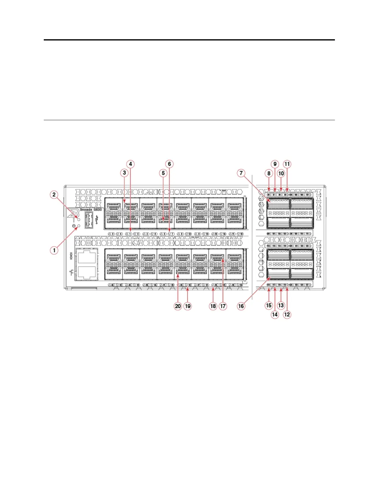
Port-side LED locations
The port-side of the switch has the following LEDs:
1. System status LED
2. System power LED
3. SFP+ (upper) port 1
4. SFP+ (upper) port 1 status LED
5. SFP+ (lower) port 7
6. SFP+ (lower) port 7 status LED
7. QSFP port 0
8. FC port 96 (QSFP 0) status LED
9. FC port 97 (QSFP 0) status LED
10. FC port 98 (QSFP 0) status LED
11. FC port 99 (QSFP 0) status LED
12. FC port 119 (QSFP 5) status LED
Figure 29. SAN128B-6 port-side LEDs
© Copyright IBM Corp. 2018 51

 Loading...