steady green LED.
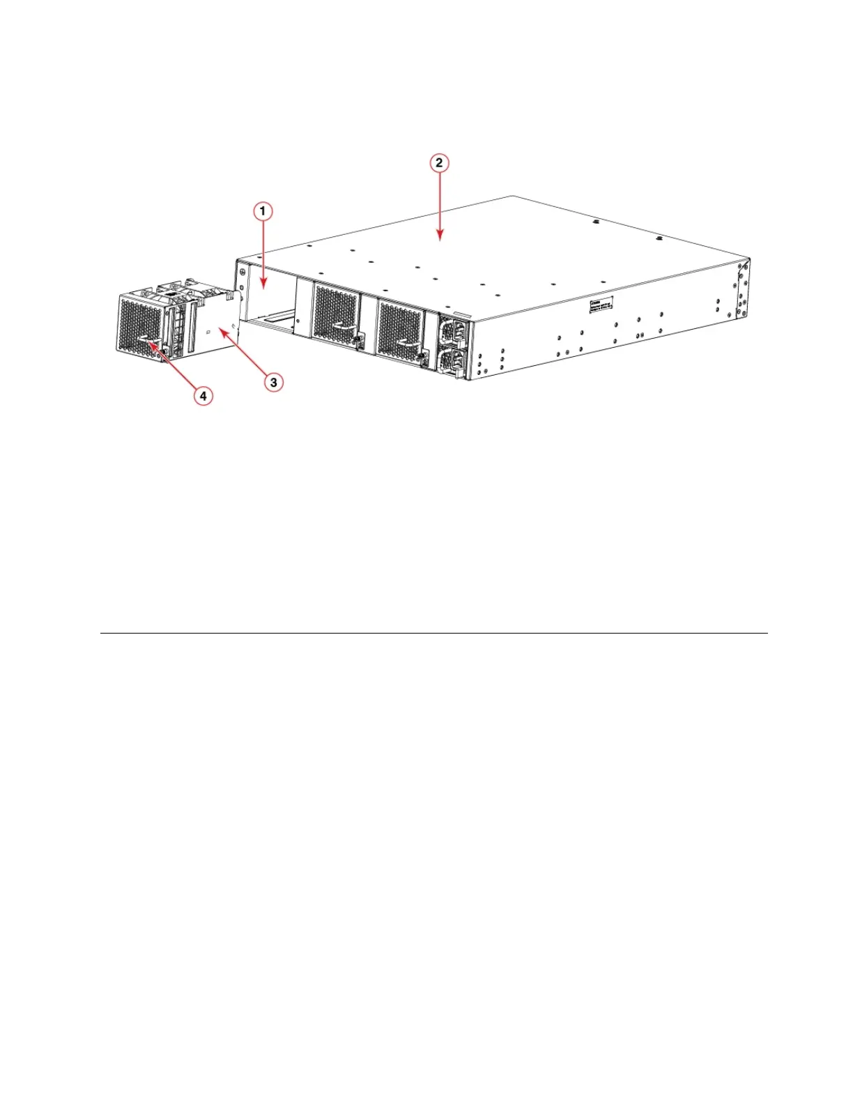
1. The SAN128B-6 device
2. Fan assembly slot 1
3. Fan assembly unit
4. Fan assembly handle
2. Using a Phillips screwdriver, unscrew the captive screw.
3. Remove the power supply and fan assembly from the chassis by pulling the handle out and away
from the chassis. The fans in the other power supply will automatically switch to high speed to
maintain adequate cooling.
Inserting a new fan assembly
Before you begin
The new fan assembly must have the same part number and airflow label (or lack thereof) as the fan
assembly already installed.
About this task
Complete the following steps to insert a new fan assembly into the chassis.
Procedure
1. To leave the device in service while installing a fan assembly, verify that the other fan assemblies (the
ones already installed) have been powered on for at least four seconds and has a steady green LED.
2. Using a Phillips screwdriver, unscrew the captive screw of the filler panel that is located in the empty
fan assembly slot.
3. Orient the new fan assembly with the captive screw on the right, as shown in the figure.
Do not force the installation. If the fan assembly does not slide in easily, ensure that it is correctly
oriented before continuing.
Figure 35. Removing a fan assembly
Fan Assemblies 69

 Loading...