EasyManuals Logo

IBM Storwize V5000 User Manual

IBM Storwize V5000
80 pages
To Next Page IconTo Next Page
To Previous Page IconTo Previous Page
Page #30 background imageLoading...
Page #30 background image
__ v Drives
__ v Power cords for connection to wall sockets
Options applicable to expansion enclosures
Note: All options other than cables are preinstalled.
__ v Expansion enclosure attachment cables
__ v Drives
__ v Power cords for connection to wall sockets
Identify the hardware components
The following graphics identify the hardware components and port locations for
the control enclosure and expansion enclosure on Storwize V5000 systems.
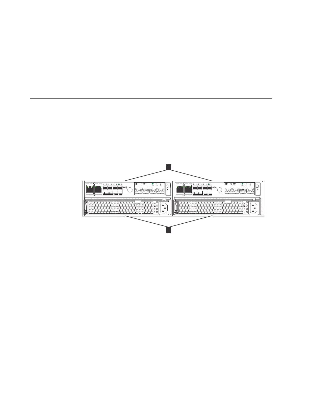
Control enclosure components
Figure 1 shows the rear view of a control enclosure and identifies the location of
the power supply units and node canisters.
Data ports
1 2
6
1
2
1
2
OK
IN
1 2
3
4
6
1
2
1
2
OK
IN
3
4
v5000009
1
2
Figure 1. Rear view of a Storwize V5000 control enclosure
6 Storwize V5000: Quick Installation Guide

Table of Contents

Questions and Answers:

Question and Answer IconNeed help?

Do you have a question about the IBM Storwize V5000 and is the answer not in the manual?

IBM Storwize V5000 Specifications

General IconGeneral
Storage TypeHybrid Flash Array
Maximum Drives240
Form Factor2U
ModelIBM Storwize V5000
Drive TypesSSD, HDD
RAID LevelsRAID 0, 1, 5, 6, 10
Host Interface8 Gbps Fibre Channel (FC), 12 Gbps SAS, 10 Gbps iSCSI, 16 Gbps FC
Software FeaturesThin provisioning
Drive Bays12 or 24
CacheUp to 32GB
Cache MemoryUp to 32GB
Weight30kg (66.1lb)
Power SupplyDual
CoolingRedundant cooling fans
Dimensions88mm x 482mm x 740mm (3.5in x 19in x 29.1in)

Related product manuals