4. If there is a plastic protective cover on the bottom of the microprocessor,
carefully remove it.
1
2
5. Locate the microprocessor installation tool that comes with the new
microprocessor.
6. Twist the handle of the installation tool counterclockwise so that it is in the
open position.
7. Align the triangle alignment mark on the microprocessor installation tool with
the triangle alignment mark on the microprocessor, and then place the
microprocessor on the underside of the tool so that the tool can grasp the
microprocessor correctly.
8. Twist the handle of the installation tool clockwise to secure the microprocessor
in the tool.
Note: You can pick up or release the microprocessor by twisting the
microprocessor installation tool handle.
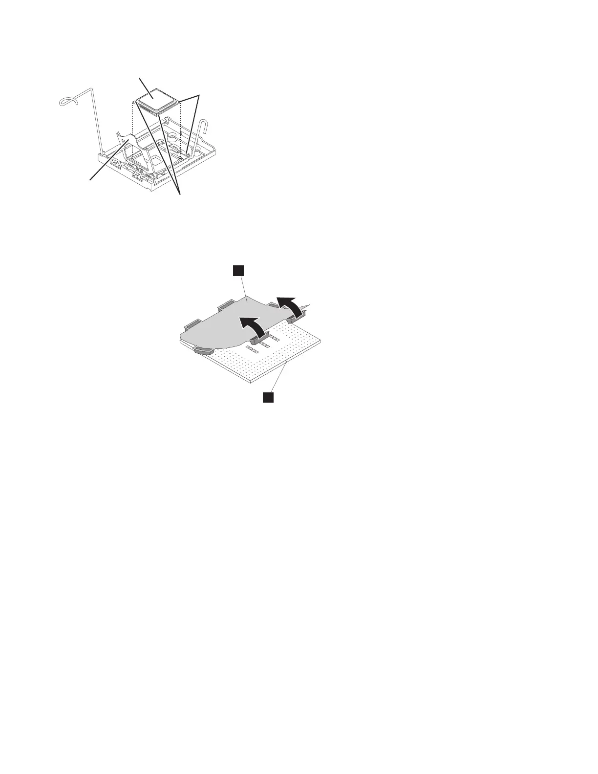
Alignment
triangles
Notches
Microprocessor
bracket frame
Microprocessor
sonas215
Figure 41. Aligning the microprocessor
144 Storwize V7000 Unified: Problem Determination Guide Version
 Loading...


