The first step is to determine the state of the control enclosure, which includes its
power supply units, batteries, and node canisters. Your control enclosure is
operational if you can manage the system using the management GUI. You might
also want to view the status of the individual power supply units, batteries, or
node canisters.
Find the control enclosure for the system that you are troubleshooting. There is one
control enclosure in a system. If you are unsure which one is the control enclosure,
go to “Procedure: Identifying which enclosure or canister to service” on page 196.
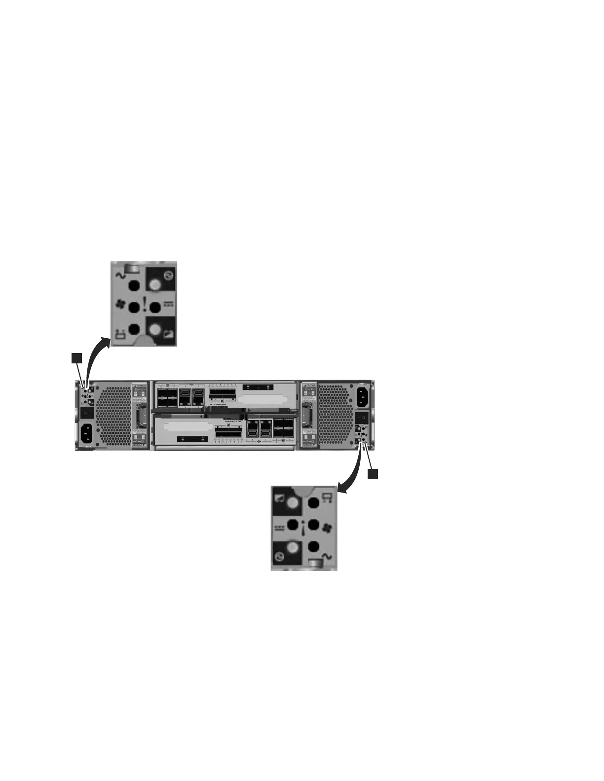
1. Use the state of the ac power failure, power supply OK, fan failure, and dc
power failure LEDs on each power supply unit in the enclosure to determine if
there is power to the system, or if there are power problems. Figure 47 shows
the LEDs on the power supply unit for the 2076-112 or 2076-124. The LEDs on
the power supply units for the 2076-312 and 2076-324 are similar, but they are
not shown here.
svc00670
1
1
Figure 47. LEDs on the power supply units of the control enclosure
Chapter 5. Control enclosure 199
 Loading...


