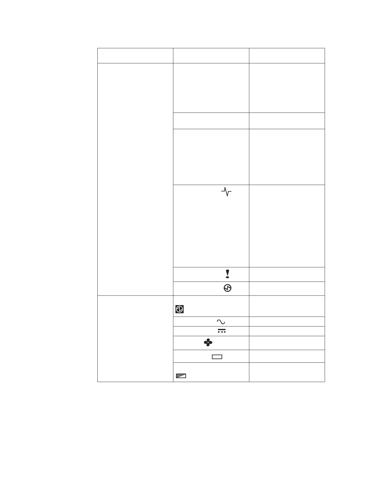
Table 50. LED status when control enclosure is powered on (continued)
Hardware component LED name
If power on and no fault is
detected
Node canister, rear. The
reference to the top and
bottom locations applies to
canister 1, which is the upper
canister. The LED locations
are inverted for canister 2,
which is the lower canister.
Fibre Channel port If the Fibre Channel port is
used: One or more LEDs are
on or flashing per port. The
LEDs are located between
the Fibre Channel ports. The
arrow-shaped LEDs point
toward the affected port.
Ethernet port, if used One or more LEDs are on
per port.
SAS ports When a SAS port is
functioning correctly, all four
green LEDs above the port
are on. If no cable is plugged
into the port, or if the
canister at either end of the
cable is not yet fully started,
the LEDs are not on.
System status, left
LED is flashing or on. The
status is on if the node
canister is an active member
of a clustered system. The
LED is flashing if the node
canister is in service or
candidate state. If the LED is
off, the node canister might
still be booting up. Wait up
to 5 minutes for the node
canister to complete booting
up.
Fault status, middle
LED is off.
Power status, right
LED is on.
Power supply unit, control
enclosure. The reference to
the left and right locations
applies to power supply unit
1, which is the left power
supply. The LED locations
are inverted for power
supply unit 2, which is the
right power supply.
Power supply, upper right
LED is on.
ac power failure
LED is off.
dc power failure
LED is off.
Fan failure
LED is off.
Battery failure
+
-
LED is off
Battery good, lower right
+
-
LED is on or flashing.
Attention: Do not go to the next section until the LEDs are in the required states.
If any error lights are displayed, see the Storwize V7000 Unified Problem
Determination Guide documentation CD for more information about light path
issues.
File module power features:
104 IBM Storwize V7000 Unified: Adding Storwize V7000 File Modules to an existing Storwize V7000 system 2073-720

 Loading...


