EasyManuals Logo

IBM Storwize V7000 Unified User Manual

IBM Storwize V7000 Unified
152 pages
To Next Page IconTo Next Page
To Previous Page IconTo Previous Page
Page #123 background imageLoading...
Page #123 background image
1. Power on the control enclosure, if it is not already powered on and configured.
Use the power switch on each of the two power supply units, located in the
back of the enclosure.
2. UseTable 50 to verify the state of the LEDs on the system. Verify that no faults
are detected.
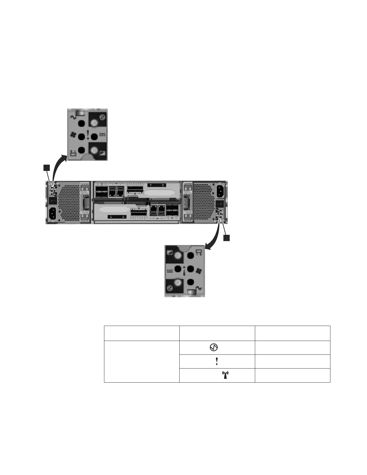
Figure 62 shows the location of the LEDs on the power supply units in the rear of
the control enclosure.
Table 50. LED status when control enclosure is powered on
Hardware component LED name
If power on and no fault is
detected
Left enclosure end cap, front
of enclosure
Power, top
LED is on.
Fault, middle
LED is off.
Identify, bottom
LED is off.
svc00670
1
1
Figure 62. LEDs on the power supply units of the control enclosure
Chapter 5. Performing the hardware installation 103

Table of Contents

Other manuals for IBM Storwize V7000 Unified

Questions and Answers:

Question and Answer IconNeed help?

Do you have a question about the IBM Storwize V7000 Unified and is the answer not in the manual?

IBM Storwize V7000 Unified Specifications

General IconGeneral
ModelIBM Storwize V7000 Unified
Storage TypeUnified Storage
RAID LevelsRAID 0, 1, 5, 6, 10
Form Factor2U
Drive Types SupportedSAS, SSD
Maximum Drives504
Network ProtocolsiSCSI, FC, FCoE
Drive Bays24 per enclosure
Host Interface8 Gb FC, 1 Gb/10 Gb iSCSI
File ProtocolsNFS, CIFS
Block ProtocolsiSCSI, Fibre Channel
TypeUnified Storage
Maximum Host Ports16
Operating System SupportVMware, Microsoft Windows, Linux, AIX
Data ServicesThin provisioning, replication
Power SupplyRedundant power supplies
Host Interfaces8 Gbps Fibre Channel, 10 Gbps iSCSI, 1 Gbps iSCSI

Related product manuals