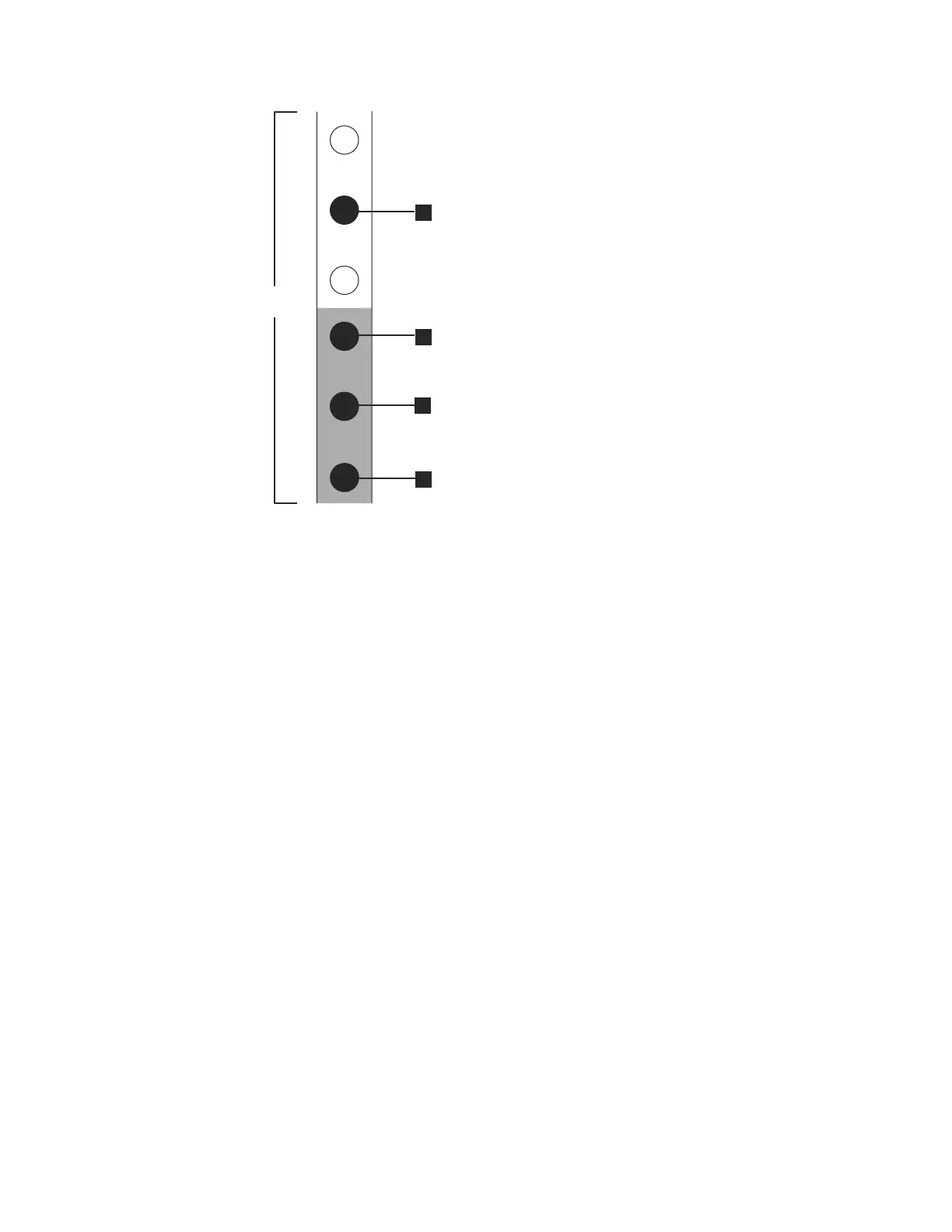
v 1 Bottom rail location pin hole
v 3 Rack mounting screw hole
v 4 Top rail location pin hole
4. Remove a clamping screw that inserts into the rack mounting hole 3, located
between the rail location pins.
5. Remove the rail location pins at positions 1 and 4, located in the rack
cabinet.
6. Repeat the steps to remove the opposite rail to the rack cabinet.
7. Repeat the procedure for each additional enclosure.
Installing the enclosure and rails
To install the support rails, perform the following steps:
1. Locate the rack mounting rails and screws.
The rail assembly is made up of two sets of rails. One set of rails is already
installed, or preinstalled, on the sides of the enclosures. The other set of rails
must be installed in the rack cabinet. The rails on the sides of the enclosures
slide into the rails that are installed in the rack cabinet.
2. Working at the front of the rack cabinet, identify the two standard rack units
of space in the rack into which you want to install the support rails.
Figure 31 on page 77 shows two rack units with the front mounting holes
identified.
2 Units
1
2
3
4
svc00695
Figure 30. Hole locations in the front of the rack
76 IBM Storwize V7000 Unified: Adding Storwize V7000 File Modules to an existing Storwize V7000 system 2073-720

 Loading...


